Broadband Circularly Polarized Panel Array Antenna

An array antenna and circularly polarized technology, applied in the field of broadband circularly polarized millimeter-wave flat panel array antennas, can solve the problem that millimeter-wave circularly polarized antennas are difficult to take into account broadband, high efficiency and array formation, etc., to achieve low cost and low cost. The effect of the section

Active Publication Date: 2018-01-12
UNIV OF ELECTRONICS SCI & TECH OF CHINA
View PDF4 Cites 2 Cited by
  • Summary
  • Abstract
  • Description
  • Claims
  • Application Information

AI Technical Summary

Problems solved by technology

[0008] The purpose of the present invention is to solve the problem that the existing millimeter-wave circularly polarized antennas are difficult to take into account broadband, high efficiency and array formation, and to provide a wide-band circularly polarized panel array antenna

Method used


Image

  • Broadband Circularly Polarized Panel Array Antenna
  • Broadband Circularly Polarized Panel Array Antenna
  • Broadband Circularly Polarized Panel Array Antenna

Examples


Embodiment Construction

[0027] The present invention will be described in further detail below in conjunction with specific embodiments and accompanying drawings.

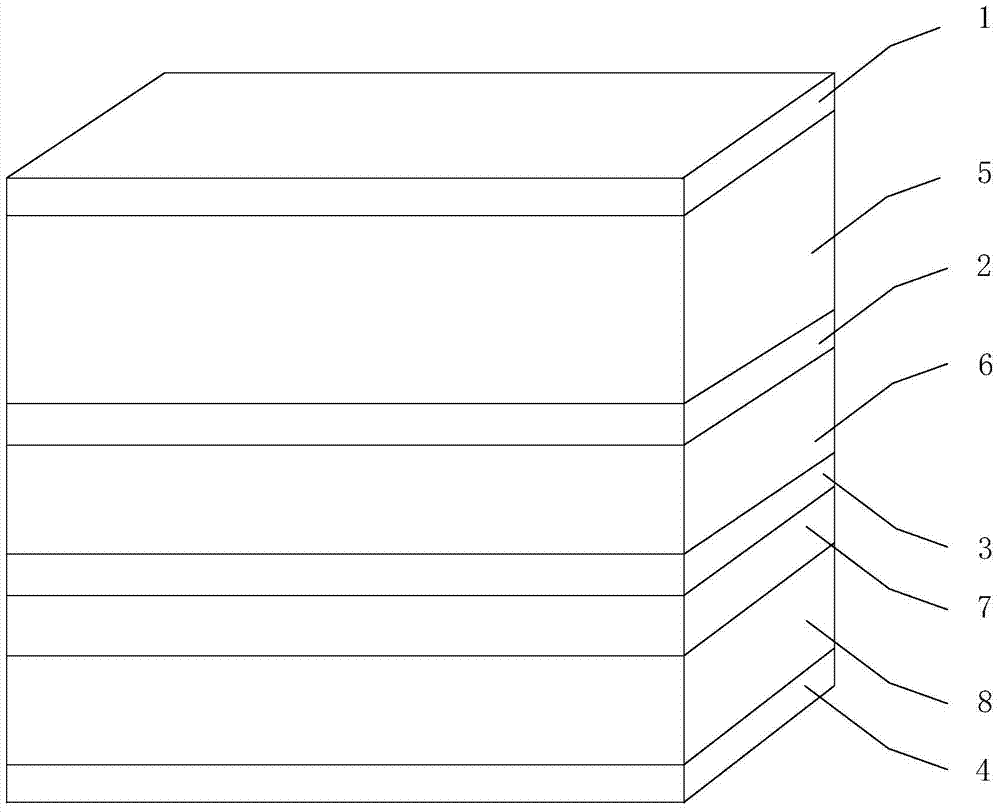
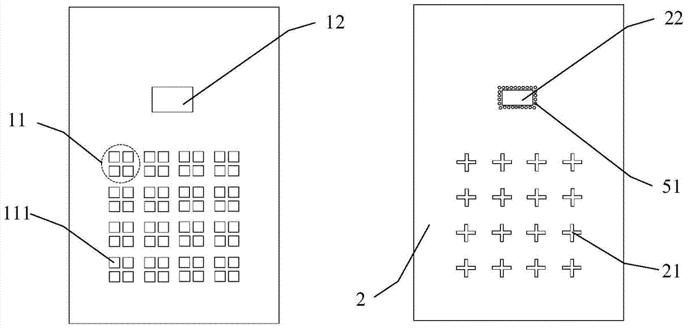
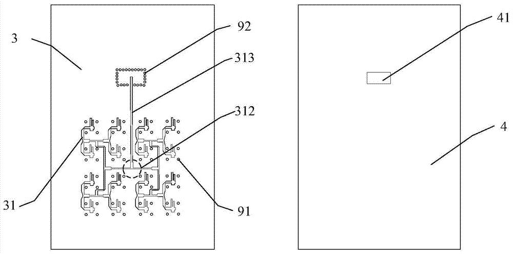
[0028] Example: such as Figure 1~4 As shown, a broadband circularly polarized panel array antenna is characterized in that the first metal copper clad layer 1, the first dielectric layer 5, the second metal copper clad layer 2, and the second dielectric layer 6 are sequentially stacked from top to bottom , the third metal copper clad layer 3 , the third dielectric layer 7 , the fourth dielectric layer 8 , and the fourth metal copper clad layer 4 . The microstrip radiating unit 11 and the SIW short circuit block 12 are etched on the first metal copper clad layer 1; the first dielectric layer 5 is distributed through it, and the two ends are respectively connected with the first metal copper clad layer 1 and the second metal copper clad layer 2 connected metallized holes 51 of the first type, which are located directly below the SIW short...


PUM


Abstract

The invention belongs to the technical field of design and manufacture of millimeter-wave circularly polarized antennas, and is used to solve the problem that the existing millimeter-wave circularly polarized antennas are difficult to take into account broadband, high efficiency and array formation, and provides a wide-band circularly polarized flat panel array antenna. The present invention adopts a novel 90° phase delay line to feed the cross groove, and four parasitic patches added above the cross groove are used to increase the gain of the antenna unit and improve the 3dB axial ratio bandwidth. The designed 90° The phase delay line has three independent branches, which are used for phase delay, amplitude compensation and matching adjustment respectively; and a set of short-circuit metal holes are designed beside the strip line to effectively suppress the propagation of the TEM mode outside the feeding network area, greatly The unit mutual coupling is reduced, and the performance of the array array is guaranteed; and the antenna of the present invention is processed by a multi-layer PCB board, which has the advantage of low cost, and is suitable for millimeter-wave large-scale circularly polarized array arrays, and solves the problem of circular poles in the millimeter-wave frequency band. It is difficult to balance the antenna efficiency and axial ratio bandwidth.

Description

technical field [0001] The invention belongs to the technical field of design and manufacture of millimeter-wave circularly polarized antennas, and in particular relates to a wide-band circularly polarized millimeter-wave panel array antenna. Background technique [0002] In a wireless communication system, the circular polarization working mode has anti-multipath effect, and compared with the linear polarization, no polarization adjustment device is needed. With the increase of wireless communication frequency, the application requirements of millimeter-wave circularly polarized antennas are becoming increasingly strong. [0003] There are mainly three ways to implement circularly polarized antennas: single-feed, multi-feed, and external circular polarizers. The feeding network of the single-feed antenna is simple, and it is easy to realize a compact and high-efficiency array. The disadvantage is that the 3dB axial ratio bandwidth of the single-feed circularly polarized an...

Claims


Application Information

Patent Timeline
Patent Type & Authority Patents(China)
IPC IPC(8): H01Q1/38H01Q13/06H01Q13/08H01Q21/00
Inventor 程钰间吴杰刘小亮薛飞
Owner UNIV OF ELECTRONICS SCI & TECH OF CHINA
Why Eureka
Try Eureka