Popping-pulling type cotton slitting machine

A cotton opener, pop-pull technology, applied in the field of pop-pull cotton opener, can solve the problem of different cotton knocking effects, and achieve the effect of easy beating

Active Publication Date: 2020-05-19
南安市英钗工业设计有限公司
View PDF7 Cites 1 Cited by
  • Summary
  • Abstract
  • Description
  • Claims
  • Application Information

AI Technical Summary

Problems solved by technology

[0005] The purpose of the present invention is to provide a spring-pull cotton opener that can evenly beat the cotton in order to solve the problem that the beating devices used in some traditional cotton opening processes have different knocking effects on cotton everywhere.

Method used


Image

  • Popping-pulling type cotton slitting machine
  • Popping-pulling type cotton slitting machine
  • Popping-pulling type cotton slitting machine

Examples


Embodiment 1

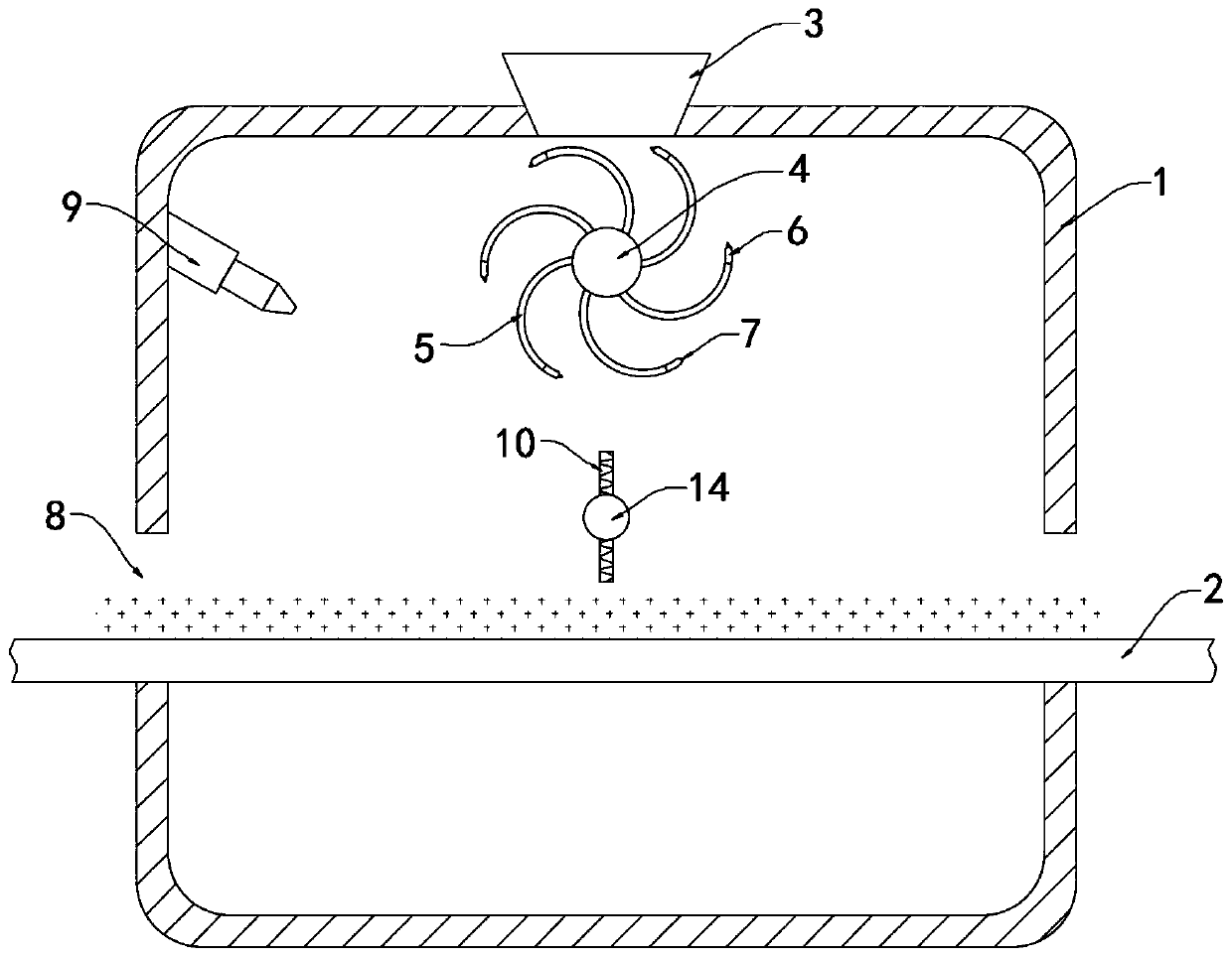
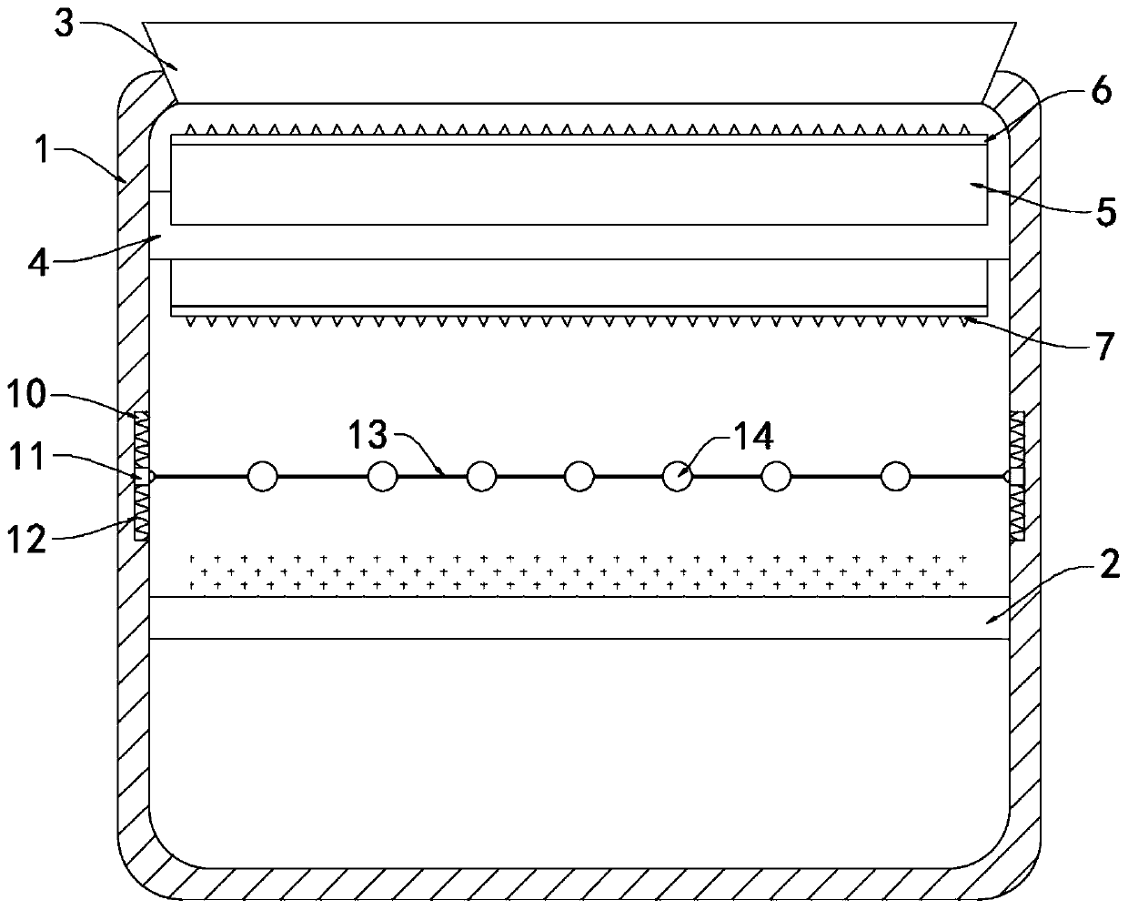
[0022] Such as Figure 1-2 As shown, a spring-pull type cotton opener includes a cotton opening box 1 and a conveyor belt 2, and the conveyor belt 2 is driven by a driving mechanism. This is the prior art and is not the subject of the invention of the device, so it will not be repeated here. The upper end of the cotton opening box 1 is fixedly connected with a strip-shaped cotton inlet hopper 3, and the cotton enters in the cotton opening box 1 through the strip-shaped cotton inlet hopper 3.

[0023] Rotate in the cotton opening box 1 and be connected with the rotating shaft 4 that horizontally arranges, and rotating shaft 4 is arranged on the just below strip-shaped cotton feeding hopper 3, and the side wall of rotating shaft 4 is fixedly connected with a plurality of arc-shaped cotton scraping plates 5 (such as figure 1 As described above), a plurality of arc-shaped cotton scraping plates 5 are arranged rotationally symmetrically with respect to the rotating shaft 4 , and a ...

Embodiment 2

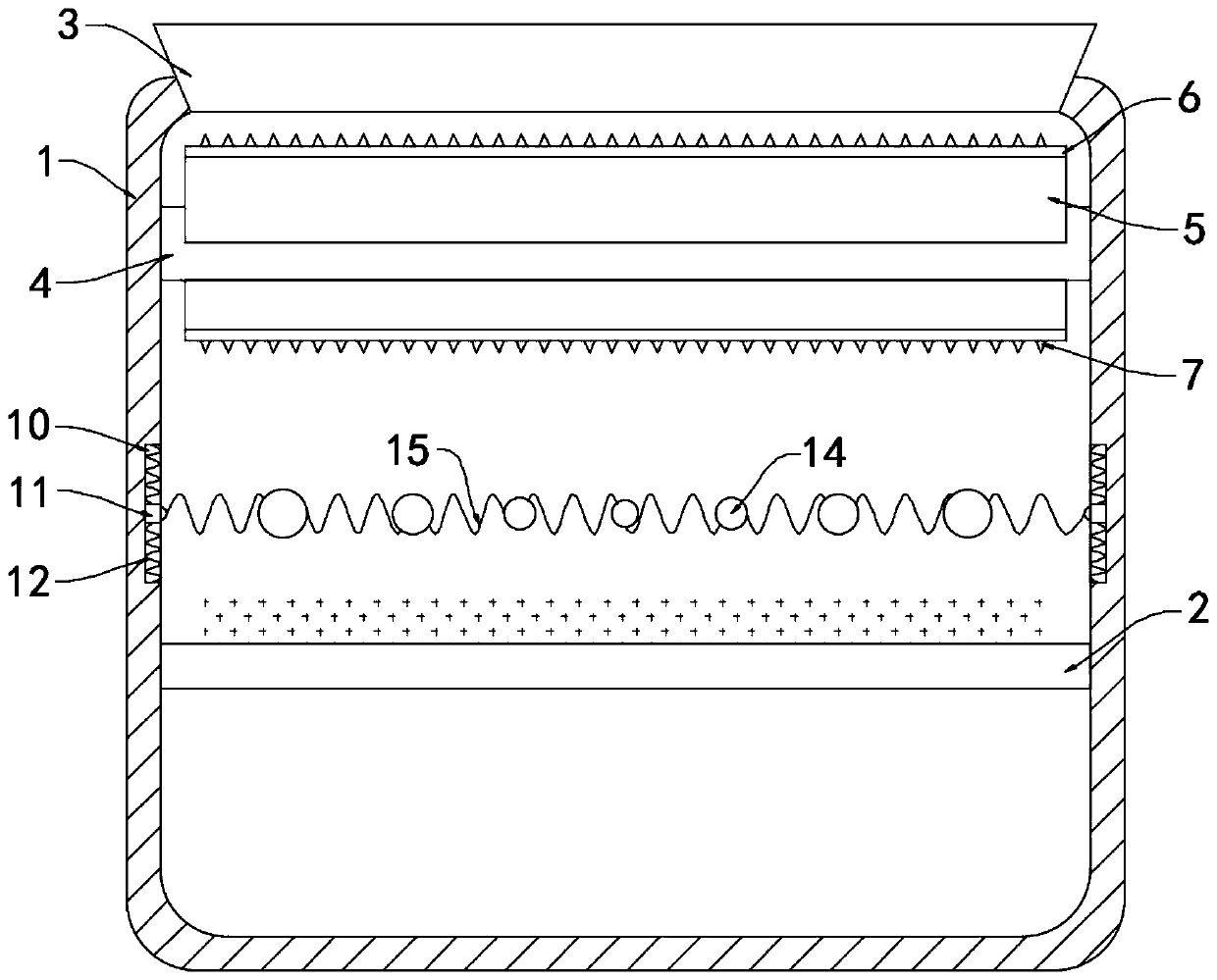
[0034] Such as image 3 As shown, the difference between this embodiment and Embodiment 1 is that: a vibrating spring 15 is fixedly connected between the two sliding blocks 11, and a plurality of counterweights that attract each other with the magnetic strip 6 are fixedly connected on the vibrating spring 15. Ball 14, the mass of a plurality of counterweight balls 14 on the vibrating spring 15 gradually increases from the middle to both sides.

[0035] In this embodiment, in the process of beating up and down of the vibrating springs, the opening and closing between the vibrating springs 15 can play the role of clamping and pulling the cotton, which can make the cotton more fluffy, and when the magnetic strip 6 is far away from the weight ball 14 At the same time, the inertia produced by the counterweight balls 14 of different masses is different, and the counterweight balls 14 on both sides have a larger mass, so the inertia is larger, which can drive the two ends of the vibr...


PUM


Abstract

The invention belongs to the textile field, and particularly relates to a popping-pulling type cotton slitting machine. The popping-pulling type cotton slitting machine comprises a cotton slitting boxand a conveyor belt, wherein the upper end of the cotton slitting box fixedly communicates with a strip-shaped cotton feeding hopper; the interior of the cotton slitting box is rotatably connected with a horizontally arranged rotating shaft; the rotating shaft is arranged under the strip-shaped cotton feeding hopper; the side wall of the rotating shaft is fixedly connected with a plurality of arc-shaped cotton scraping plates; the plurality of arc-shaped cotton scraping plates are rotationally symmetrically arranged with respect to the rotating shaft; the edge of each arc-shaped cotton scraping plate is fixedly embedded with a magnetic strip; and the side edge of each arc-shaped cotton scraping plate is fixedly connected with a plurality of uniformly distributed cotton scraping nails. Thecotton slitting machine is provided with vibration springs and a plurality of counterweight balls with different masses; in an up-down beating process of the vibration springs, the effect of clampingcotton fibers can be achieved through opening and closing of the vibration springs, and cotton can be more fluffy; and the masses of the counterweight balls on the two sides are relatively large, andinertia is relatively large, so that the situation that only the middle flapping effect is relatively good is avoided.

Description

technical field [0001] The invention belongs to the field of local textiles, in particular to a spring-pull cotton opener. Background technique [0002] In the later stage of cotton production and processing, it is necessary to make the tangled cotton soft, which is called cotton opening. Cotton opening is a relatively important step in production and processing. [0003] Some traditional cotton opening processes are completed by hand-pulling cotton beating devices. The traditional beating device uses a cam structure to control rod parts to swing along the axis to complete the beating of the cotton. However, this processing form is not only labor-intensive Large, and the beater's knocking rod usually swings along the axis, and the cotton is hit differently at each position of the beater's knocking rod, which easily makes the cotton's knocking effect different in different places, making the cotton fluffy after processing. . [0004] For this reason, we propose a spring-pul...

Claims


Application Information

Patent Timeline
Patent Type & Authority Applications(China)
IPC IPC(8): D01G9/00D01G9/14
CPCD01G9/00D01G9/14
Inventor 雷银霞
Owner 南安市英钗工业设计有限公司
Why Eureka
Try Eureka