Spinning equipment with dust collection hood

A technology of textile equipment and vacuum hood, which is applied in the field of textile dust prevention, can solve problems affecting quality and dust, and achieve good vibration and good dust removal effect

Inactive Publication Date: 2020-05-19
涟水建强纺织有限公司
0 Cites 0 Cited by

AI-Extracted Technical Summary

Problems solved by technology

Since the textile machinery equipment is a precision equipment, the dust falling into the interior will cause the dust to be rubbed onto the textile line during the operation of the machine, resulting...

Method used

Principle of work: the invention stretches the cloth by the third restriction ring 17 in the dust removal box 13, and then drives the dust removal shaft 15 to rotate the dust removal rod 16 by the motor 14, so that the dust removal rod 16 can be made to reciprocate and beat the cloth, Realize good vibration, so that the dust attached to the outside of the cloth falls, and then transported to the dust-dispersing pipe 22 through the dust suction port 18, and finally dissolves in the liquid. At the same time, the cloth is spread on the upper surface of the textile platform 4 through the first restriction ring 10 for corresponding Process treatment, the operation table 6 is equipped with a vacuum net 7 to absorb the dust on the surface of the cloth for a second time, and the dust is discharged into the water tank 21 through the negative pressure fan 19, and the first reel 1 and the second reel 2 are provided. Automatic cloth feeding and discharging can achieve good dust removal effect.
Some described dedusting rods 16 lengths are different, and described dedusting rod 16 outer surfaces are provided with dust-proof material, can...

Abstract

The invention discloses spinning equipment with a dust collection hood. The spinning equipment comprises a first reel and a second reel, wherein the first reel is fixedly arranged on the ground through a mounting base; a motor is fixedly arranged on one side of the first reel through a mounting base; the output end of the motor is fixedly connected with the first reel; a spinning platform is fixedly arranged on one side of the first reel; supporting columns are fixedly arranged at the four corners of the bottom end of the spinning platform; an operation table is fixedly arranged in the middleof the upper end of the spinning platform; a dust collection net is fixedly arranged in the middle of the operation table; a dust collection hood is fixedly connected to the lower end of the dust collection net; a dust removal pipe is fixedly connected to the lower end of the dust collection hood; first limiting rings are movably mounted on the two sides, away from the dust collection net, of theupper end of the spinning platform respectively; and a spinning device is fixedly arranged on the side face of the spinning platform through a mounting base. According to the spinning equipment, dustcollection for the spinning equipment is realized, cloth is pretreated in a dust collection box, and the spinning equipment has high dust collection performance.

Application Domain

Mechanical cleaningPressure cleaning

Technology Topic

EngineeringDust control +1

Image

  • Spinning equipment with dust collection hood
  • Spinning equipment with dust collection hood
  • Spinning equipment with dust collection hood

Examples

  • Experimental program(1)

Example Embodiment

[0017] The technical solutions in the embodiments of the present invention will be clearly and completely described below in conjunction with the accompanying drawings in the embodiments of the present invention. Obviously, the described embodiments are only a part of the embodiments of the present invention, rather than all the embodiments. Based on the embodiments of the present invention, all other embodiments obtained by those of ordinary skill in the art without creative work shall fall within the protection scope of the present invention.
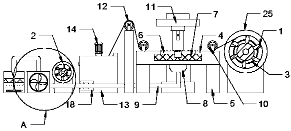
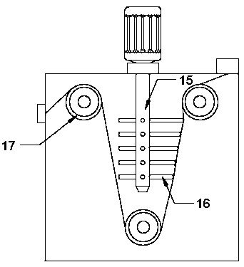
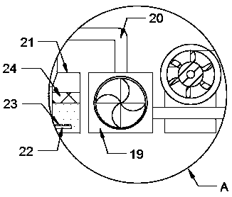
[0018] See Figure 1-3 , The present invention provides a technical solution: a textile equipment with a dust hood, comprising a first reel 1 and a second reel 2, the first reel 1 is fixed on the ground through a mounting seat, the first reel 1 One side is fixedly provided with a motor 3 through a mounting seat, the output end of the motor 3 is fixedly connected to the first reel 1, a textile platform 4 is fixedly provided on one side of the first reel 1, and the bottom end of the textile platform 4 is fixed at four corners A support column 5 is provided, the upper middle of the textile platform 4 is fixedly provided with an operation table 6, the middle of the operation table 6 is fixedly provided with a dust suction net 7, and the lower end of the dust suction net 7 is fixedly connected with a dust suction cover 8, so The lower end of the dust suction hood 8 is fixedly connected with a dust removal pipe 9, the upper end of the textile platform 4 is away from the dust suction net 7 and a first restricting ring 10 is movably installed on both sides, and the textile platform 4 is fixedly provided with a textile device through a mounting seat. 11. A second restricting ring 12 is fixedly arranged on the side of the textile platform 4 away from the first reel 1, and a dust box 13 is fixedly arranged on the side of the second restricting ring 12 away from the textile platform 4, and the upper end of the dust box 13 passes The mounting seat is fixedly installed with a motor 14. The output end of the motor 14 is fixedly provided with a dust removal shaft 15, a plurality of dust removal rods 16 are fixedly provided on the outside of the dust removal shaft 15, and the dust removal box 13 is movably installed with three third limits through bearings. Ring 17, a dust suction port 18 is installed on the outside of the dust removal box 13, and the dust suction port 18 is fixedly communicated with the dust removal pipe 9, and a second reel 2 is fixedly provided on the side of the dust removal box 13 away from the textile platform 4 through a mounting seat A negative pressure fan 19 is fixedly provided on the side of the second reel 2 away from the dust removal box 13, and the end of the dust removal pipe 9 away from the dust removal box 13 is fixedly connected to the negative pressure fan 19, and the upper end of the negative pressure fan 19 is fixedly connected with an output In the pipe 20, a water tank 21 is fixedly arranged on the side of the negative pressure fan 19 away from the second reel 2, and a dust diffuser 22 is fixedly arranged inside the water tank 21, and a plurality of air outlet holes 23 are opened on the upper surface of the dust diffuser 22, An isolation net 24 is fixedly arranged in the middle of the water tank 21, and the dust dispersing pipe 22 is fixedly connected with the output pipe 20.
[0019] The lengths of the several dust removal rods 16 are different, and the outer surface of the dust removal rod 16 is provided with dust-proof material, which can prevent dust from attaching to the outer surface of the dust removal rod 16 and affect the dust removal effect of the cloth; the dust removal rod 16 is installed on the side away from the motor 14 A third restriction ring 17, two third restriction rings 17 are respectively installed on both sides of the dust removal rod 16, which can direct the cloth to facilitate the dust removal rod 16 to beat and remove dust; the first reel 1 and the second reel 2 A turntable 25 is installed on the outside. The outer surface of the turntable 25 is provided with non-slip materials, which is convenient for workers to adjust the position of the cloth; at least four air outlets 23 are evenly provided on the top side of the dust spreading pipes 22, which can effectively prevent dust Collect it to prevent it from spreading into the air; the outer sides of the first restriction ring 10, the second restriction ring 12, and the third restriction ring 17 are all fixedly provided with non-slip materials. The water tank 21 is designed without a cover to prevent the water tank 21 from entering The liquid is poured.
[0020] Working principle: The invention stretches the cloth through the third restriction ring 17 in the dust removal box 13, and then drives the dust removal shaft 15 to rotate the dust removal rod 16 through the motor 14, so that the dust removal rod 16 can reciprocate the cloth to achieve good vibration , Make the dust attached to the outside of the cloth fall off, and then transport it to the dust diffuser 22 through the dust suction port 18, and finally dissolve in the liquid. At the same time, the cloth is spread flat on the upper surface of the textile platform 4 through the first restriction ring 10 for corresponding processing. The operation table 6 is provided with a dust suction net 7 which can secondly absorb the dust on the surface of the cloth. The dust is discharged into the water tank 21 through the negative pressure fan 19, and the first reel 1 and the second reel 2 are provided for automatic cloth cloth. Feeding and discharging can achieve good dust removal effect.
[0021] It should be noted that in this article, relational terms such as first and second are only used to distinguish one entity or operation from another entity or operation, and do not necessarily require or imply one of these entities or operations. There is any such actual relationship or order between. Moreover, the terms "include", "include" or any other variants thereof are intended to cover non-exclusive inclusion, so that a process, method, article or device including a series of elements not only includes those elements, but also includes those that are not explicitly listed Other elements of, or also include elements inherent to this process, method, article or equipment.
[0022] Although the embodiments of the present invention have been shown and described, those of ordinary skill in the art can understand that various changes, modifications, and substitutions can be made to these embodiments without departing from the principle and spirit of the present invention. And variations, the scope of the present invention is defined by the appended claims and their equivalents.

PUM

no PUM

Description & Claims & Application Information

We can also present the details of the Description, Claims and Application information to help users get a comprehensive understanding of the technical details of the patent, such as background art, summary of invention, brief description of drawings, description of embodiments, and other original content. On the other hand, users can also determine the specific scope of protection of the technology through the list of claims; as well as understand the changes in the life cycle of the technology with the presentation of the patent timeline. Login to view more.

Similar technology patents

Cyclone type dust removing device of grain dust-removing machine

InactiveCN106216111AThorough dust removalGood dust removal effect
Owner:WUXI FUMEI LIGHT ALLOY TECH

Convenient-to-adjust knitting machine

Owner:HUZHOU LINGHU ZHONGZHAO JINHUI SILK WEAVING FACTORY

Ion fan

InactiveCN111148333AGood dust removal effecteasy discharge
Owner:华静

Damping bush for steering mechanism of vehicle

InactiveCN110886788AImprove fixationgood vibration
Owner:DMC 股份有限公司

Electrode plate structure of novel electrostatic adsorption type air purifier

PendingCN107497604AExtended travel pathGood dust removal effect
Owner:上海钉点智能科技有限公司

Classification and recommendation of technical efficacy words

  • good vibration
  • Good dust removal effect

Damping bush for steering mechanism of vehicle

InactiveCN110886788AImprove fixationgood vibration
Owner:DMC 股份有限公司

Dust remover of air conditioner

Owner:苏州腾辉环保科技有限公司

Uniform-feeding rice impurity removing equipment

InactiveCN108339751AGood dust removal effectavoid reprocessing
Owner:滁州广洋湖米业有限公司

Dust removal device for industrial waste gas

InactiveCN108355417AGood dust removal effect
Owner:ANHUI HANSHAN COUNTY TIANSHUN ENVIRONMENTAL PROTECTION EQUIP

Part machining cutting device with dust removing function

InactiveCN107262811Aclean completelyGood dust removal effect
Owner:CHENZHOU JINTONG INFORMATION TECH CO LTD
Why Eureka
Try Eureka