Operation station with rotary supporting system

A technology of rotating support and operation station, applied in the field of machine tool operation station, can solve the problems of single fixing method, self-evident machine tool, affecting processing efficiency, etc., to achieve the effect of easy orientation adjustment, good support effect, and improved processing efficiency

Active Publication Date: 2016-12-07
成都艾威机械有限公司
View PDF10 Cites 0 Cited by
  • Summary
  • Abstract
  • Description
  • Claims
  • Application Information

AI Technical Summary

Problems solved by technology

[0003] The operating station, as an operating part for CNC machine tools or machining centers, undertakes a very important input function. Although it is not as eye-catching as machine tool tools, its importance relative to machine tools is also self-evident. In the existing In the technology, the commonly used operation station has a single fixing method, and is usually clamped on the machine tool frame by clamps. Although this clamping structure is very simple, it is easy to be damaged, and it is also prone to occurrence of difficult alignment during clamping. In case of damage, it is not easy to operate and affects the processing efficiency

Method used


Image

  • Operation station with rotary supporting system
  • Operation station with rotary supporting system
  • Operation station with rotary supporting system

Examples


Embodiment Construction

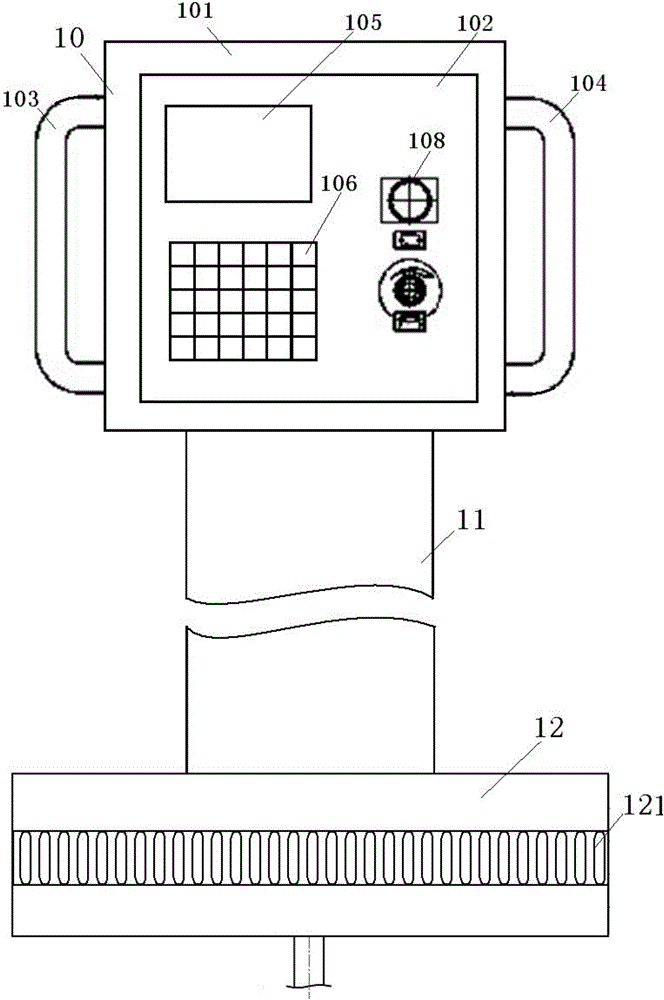
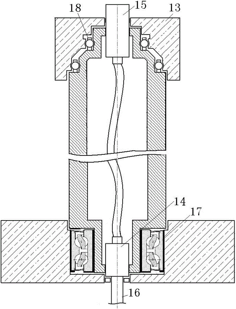
[0025] see figure 1 and 2 , shows an operator station with a rotating support system according to the invention.

[0026] The described operating station with rotating support system includes an operating station host 10 and rotating supporting system, see figure 1 , the operation station host 10 includes a square host body 101, the host body 101 is built with an operating system, its front surface is provided with an operation panel 102, and the left and right sides of the host body 101 are respectively provided with a left handrail 103 and a right handrail. Handrail 104, so that the operator holds and operates, and the operation panel 102 is embedded with a display screen 105, a plurality of operation buttons 106 and at least one indicator light 107, and the display screen 105, a plurality of operation buttons 106 and at least one The indicator light 107 is connected to the operating system to provide real-time information display, data transmission and parameter setting, ...


PUM


Abstract

The invention discloses an operation station with a rotary supporting system. The operation station comprises an operation station main machine and the rotary supporting system, wherein the operation station main machine comprises a main machine body; an operation system is arranged inside the main machine body; an operation panel is arranged on the front surface of the main machine body; a left handrail is arranged at the left side of the main machine body, and a right handrail is arranged at the right side of the main machine body; a display, a plurality of operation buttons and at least one indicator light are embedded in the operation panel, wherein the display, the plurality of operation buttons and the at least one indicator light are connected to the operation system; the rotary supporting system comprises a hollow supporting rod and a support; an upper support sleeve is rotatably supported at the upper end of the hollow supporting rod through an upper supporting structure; the operation station main machine is supported on the upper support sleeve; and the lower end of the hollow supporting rod is rotatably supported on the support through a support bearing assembly, and the bi-directional rotary supporting of the upper and lower ends is achieved. According to the operation station, the structure is simple, the operation is convenient, comprehensive rotary supporting can be achieved, the direction is conveniently adjusted, the processing efficiency can be improved, and the application range is enlarged.

Description

technical field [0001] The invention relates to the technical field of machine tool operating stations, in particular to an operating station with a rotating support system. Background technique [0002] my country's machine tool industry has grown from scratch, transformed from extensive to precise, and has formed a relatively complete system of product research and development and production. [0003] The operating station, as an operating part for CNC machine tools or machining centers, undertakes a very important input function. Although it is not as eye-catching as machine tool tools, its importance relative to machine tools is also self-evident. In the existing In the technology, the commonly used operation station has a single fixing method, and is usually clamped on the machine tool frame by clamps. Although this clamping structure is very simple, it is easy to be damaged, and it is also prone to occurrence of difficult alignment during clamping. If it is damaged, i...

Claims


Application Information

Patent Timeline
Patent Type & Authority Applications(China)
IPC IPC(8): B23Q1/00B25H5/00
CPCB23Q1/0009B25H5/00
Inventor 李知密梁吉平朱洪李青
Owner 成都艾威机械有限公司
Why Eureka
Try Eureka