Wall skin removing device for building construction

A technology of building construction and removal device, applied in construction, building maintenance, building structure and other directions, can solve the problems of inconvenient use control adjustment, inability to remove and chop the wall skin, unfavorable recycling and other problems, and achieve the improvement effect and application. Scope, easy eradication, easy cutting effect

Inactive Publication Date: 2020-05-19
宜昌东阳建设工程有限公司
View PDF7 Cites 3 Cited by
  • Summary
  • Abstract
  • Description
  • Claims
  • Application Information

AI Technical Summary

Problems solved by technology

[0003] When constructing the old wall surface, it is necessary to remove the wall surface in advance, and then carry out the construction work again. The existing wall skin removal device has the following disadvantages: it is inconvenient to use the control and adjustment, and it is impossible to remove and cut the wall skin well. Broken, not conducive to subsequent recycling

Method used


Image

  • Wall skin removing device for building construction
  • Wall skin removing device for building construction
  • Wall skin removing device for building construction

Examples


Embodiment 1

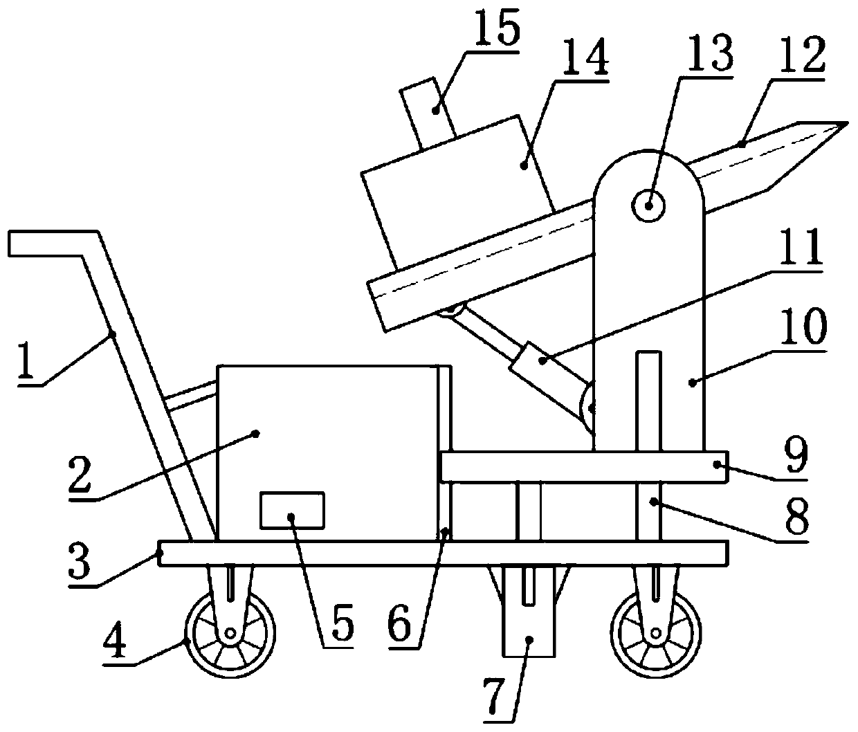
[0019] see figure 1 , in an embodiment of the present invention, a wall skin removal device for building construction includes a base plate base 3, the left and right sides of the top of the base base base 3 are respectively provided with storage boxes 2 and mounting seats 9, the bottom of the base base base 3 An elevating telescopic cylinder 7 for driving the mounting base 9 to move up and down is installed, and two side frames 10 are installed and fixed on the top of the mounting base 9, and the mounting base 9 on the outside of the two side frames 10 is also equipped with a guide for sliding. Rod 8, the lower end of guide rod 8 is fixed on the base plate seat 3, can play the guiding effect to mounting seat 9 by guide rod 8, and guide rod 8 is located at the outside of side frame 10, guide support effect is good.

[0020] The upper part between the two side frames 10 is rotatably equipped with a wall skin shovel 12 through a support shaft 13, the wall skin shovel 12 can be s...

Embodiment 2

[0026] see Figure 1-3 , the difference between this embodiment and embodiment 1 is:

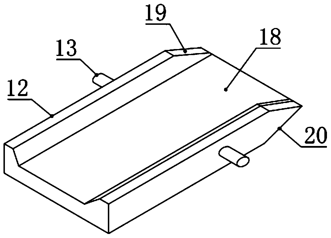
[0027] In this example, if image 3 As shown, the top of the wall skin shovel 12 is provided with a material guide groove 18, and the longitudinal section of the material guide groove 18 is an isosceles ladder shape with a large upper part and a smaller lower one, which is beneficial to the sliding of the wall skin; the wall skin shovel plate 12 The upper side of the right end of the wall is provided with an upper slope 19, and the lower side of the right end of the wall skin shovel plate 12 is provided with a lower slope 20, and the right end of the upper slope 19 and the lower slope 20 is connected, and by setting the upper slope 19 and the lower slope 20, The wall covering can be scraped off.

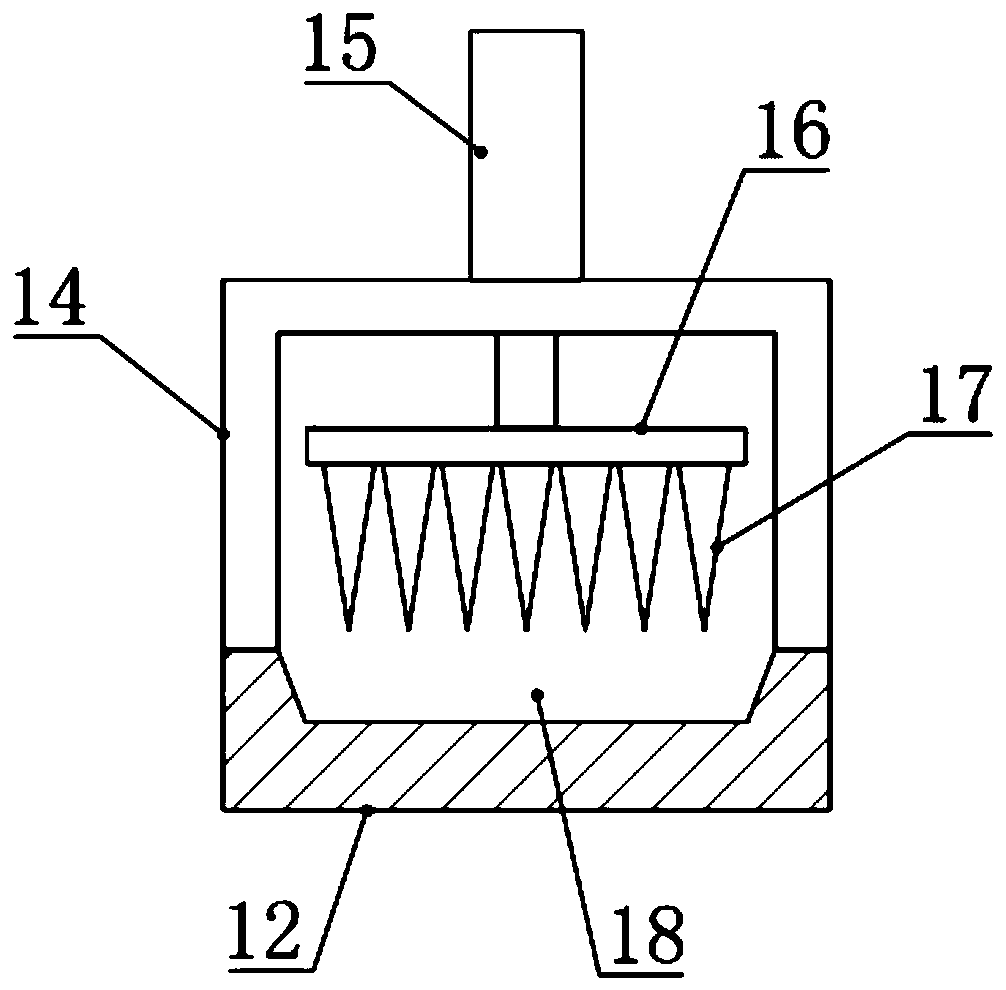
[0028] In this example, if figure 2 As shown, the cutting mechanism includes an inverted U-shaped frame 14, a cutting telescopic cylinder 15, a mounting plate 16, and a cutting knife 17. The in...


PUM


Abstract

The invention relates to the field of building construction devices, in particular to a wall skin removing device for building construction. The device comprises a bottom plate seat, wherein a storagebox and a mounting seat are arranged on the left side and the right side of the top of the bottom plate seat respectively, a lifting telescopic cylinder used for driving the mounting seat to move upand down is mounted at the bottom of the bottom plate seat, two side frames are fixedly mounted at the top of the mounting eat, a guide rod is further arranged on the position, on the outer sides of the two side frames, of the mounting base in a matched and sliding mode, the lower end of the guide rod is fixed to the bottom plate seat, a wall skin shovel plate is rotationally mounted on the upperportion between the two side frames through a supporting shaft, an angle adjusting telescopic cylinder used for supporting and angle adjusting of the wall skin shovel plate is installed on the lower side of the left end of the wall skin shovel plate, and a cutting mechanism is further installed on the left side of the wall skin shovel plate. The device is convenient to use, control and adjust, hasgood clearing and cutting effects on the wall skin, and is beneficial to subsequent recycling treatment.

Description

technical field [0001] The invention relates to the field of building construction devices, in particular to a wall skin removal device for building construction. Background technique [0002] Building construction refers to the production activities in the implementation stage of engineering construction. It is the construction process of various buildings. It can also be said to be the process of turning various lines on the design drawings into real objects at designated locations. It includes basic engineering construction, main structure construction, roofing engineering construction, decoration engineering construction, etc. The place where the construction works is called "building construction site" or "construction site". [0003] When constructing the old wall surface, it is necessary to remove the wall surface in advance, and then carry out the construction work again. The existing wall skin removal device has the following disadvantages: it is inconvenient to us...

Claims


Application Information

Patent Timeline
Patent Type & Authority Applications(China)
IPC IPC(8): E04G23/00
CPCE04G23/00
Inventor 向军吴洪园
Owner 宜昌东阳建设工程有限公司
Why Eureka
Try Eureka