Supercharge Your Innovation With Domain-Expert AI Agents!

Vertical rotary compressor

A vertical rotary compressor technology, which is applied to rotary piston/oscillating piston pump components, mechanical equipment, machines/engines, etc., can solve the problems of the mechanical efficiency of the pump body, such as the reduction of mechanical efficiency, and achieve the purpose of improving mechanical efficiency and reducing Abrasion and the effect of improving the coefficient of performance

Active Publication Date: 2020-05-19
SHANGHAI HITACHI ELECTRICAL APPLIANCES CO LTD
View PDF17 Cites 0 Cited by
  • Summary
  • Abstract
  • Description
  • Claims
  • Application Information

AI Technical Summary

Problems solved by technology

[0004] Aiming at the problems in the prior art, the present invention provides a vertical rotary compressor, which solves the problem that the mechanical efficiency of the pump body decreases due to abrasion of the lower thrust surface and the lower cylinder head

Method used


Image

  • Vertical rotary compressor
  • Vertical rotary compressor
  • Vertical rotary compressor

Examples


Embodiment Construction

[0025] Example embodiments will now be described more fully with reference to the accompanying drawings. Example embodiments may, however, be embodied in many forms and should not be construed as limited to the embodiments set forth herein. Rather, these embodiments are provided so that this disclosure will be thorough and complete, and will fully convey the concept of the example embodiments to those skilled in the art. The same reference numerals denote the same or similar structures in the drawings, and thus their repeated descriptions will be omitted.

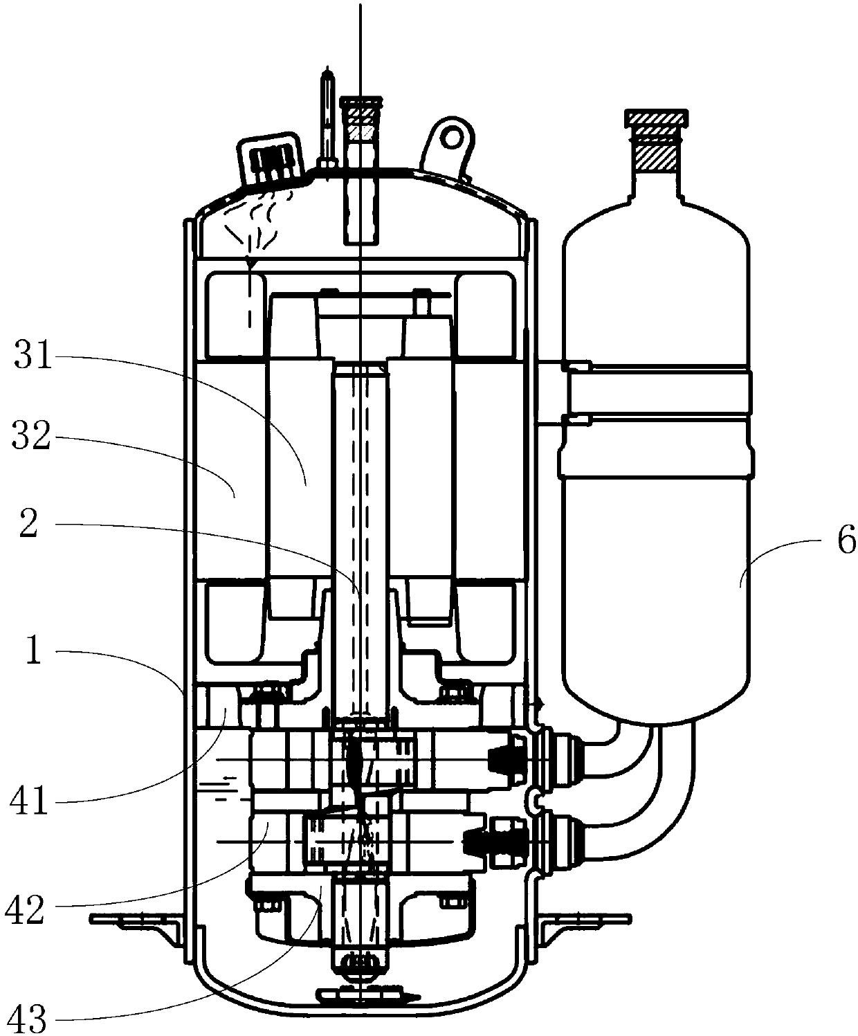
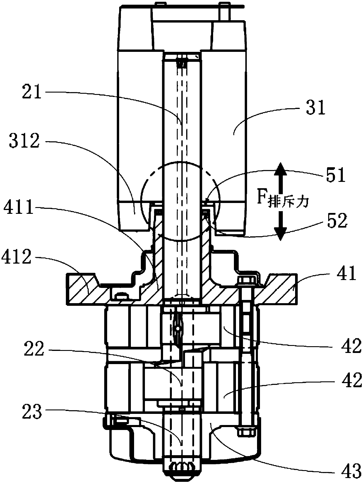
[0026] refer to figure 1 and figure 2 As shown, in one embodiment of the present invention, the vertical rotary compressor includes:

[0027] Housing 1; specifically includes an intermediate housing, a top cover at the top of the compressor and a bottom cover at the bottom of the compressor (not specifically marked in the figure), the intermediate housing, the top cover, and the bottom cover form a sealed housing 1 .

...


PUM

PropertyMeasurementUnit
Spacingaaaaaaaaaa

Abstract

The invention provides a vertical rotary compressor. The vertical rotary compressor comprises a shell, a crankshaft, a rotor and an upper cylinder cover; the crankshaft is contained in the shell, andthe crankshaft is provided with a long shaft part, an eccentric part and a short shaft part which are sequentially connected from top to bottom; the rotor is arranged at the upper end of the long shaft part of the crankshaft in a sleeving mode, the upper cylinder cover comprises a bearing part and a flange part, the bearing part is arranged at the lower end of the long shaft part of the crankshaftin a sleeving mode, and the flange part extends outwards by taking the bearing part as a circle center; and a first magnetic pole is fixed to the lower end face of an iron core of the rotor, a secondmagnetic pole is fixed to the upper end face of the bearing part of the upper cylinder cover, the first magnetic pole and the second magnetic pole are the same poles and opposite to generate interactive repulsive force, and resultant force of motor magnetic core height difference axial force, skewed slot force axial force, rotor self-weight and crankshaft self-weight is counteracted to reduce thepressure between a thrust surface and a lower cylinder cover, so that the abrasion is reduced, the pump body mechanical efficiency is improved and the compressor performance coefficient is increased.

Description

technical field [0001] The invention relates to the technical field of air conditioning, in particular to a vertical rotary compressor. Background technique [0002] In a rotary compressor, due to the resultant force of the axial force of the height difference of the motor core, the axial force of the chute force, the self-weight of the rotor and the self-weight of the crankshaft, the lower cylinder head is pressed through the lower thrust surface of the crankshaft. The greater the resultant force, the greater the resultant force of the crankshaft The wear of the contact surface between the lower thrust surface and the lower cylinder head is greater. Long-term wear leads to a decrease in the mechanical efficiency of the pump body and a decrease in the COP (coefficient of performance, coefficient of performance) of the compressor. [0003] It should be noted that the information disclosed in the above background technology section is only used to enhance the understanding of...

Claims


Application Information

Patent Timeline
IPC IPC(8): F04C29/00
CPCF04C29/00F04C29/0035
Inventor 周易张兴志范杰周启风
Owner SHANGHAI HITACHI ELECTRICAL APPLIANCES CO LTD
Features
  • R&D
  • Intellectual Property
  • Life Sciences
  • Materials
  • Tech Scout
  • Unparalleled Data Quality
  • Higher Quality Content
  • 60% Fewer Hallucinations
Learn More