
Semi-automatic ball filling device for retainer-free full ball bearing and ball filling method thereof

A technology of full ball bearings and cages, applied to bearing components, shafts and bearings, mechanical equipment, etc., can solve the problems of low efficiency of manual ball filling and high work intensity, so as to reduce scratches, reduce labor intensity, and ensure finished products The effect of pass rate

Pending Publication Date: 2020-05-19
余姚市新丰轴承有限公司
View PDF0 Cites 1 Cited by
  • Summary
  • Abstract
  • Description
  • Claims
  • Application Information

AI Technical Summary

Problems solved by technology

[0004] The purpose of the present invention is to address the defects of low manual ball filling efficiency and high work intensity in the above-mentioned prior art, and provide a semi-automatic ball filling device and ball filling method for full ball bearings without cages, which can achieve the purpose of reducing manual labor intensity

Method used


Image

  • Semi-automatic ball filling device for retainer-free full ball bearing and ball filling method thereof
  • Semi-automatic ball filling device for retainer-free full ball bearing and ball filling method thereof
  • Semi-automatic ball filling device for retainer-free full ball bearing and ball filling method thereof

Examples


Embodiment Construction

[0034] The present invention will be further described below in conjunction with the accompanying drawings and specific embodiments, but not as a limitation of the present invention.

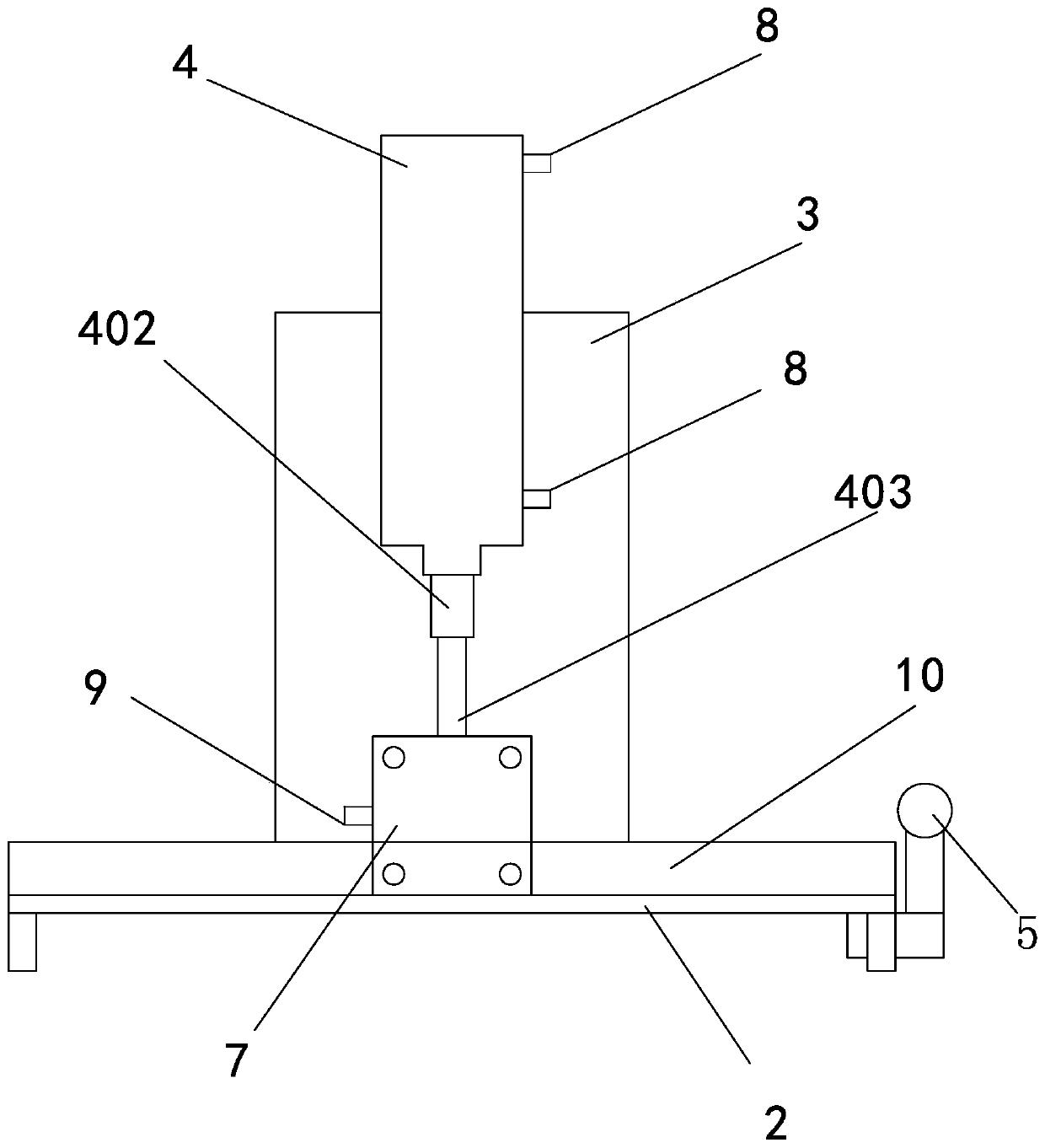
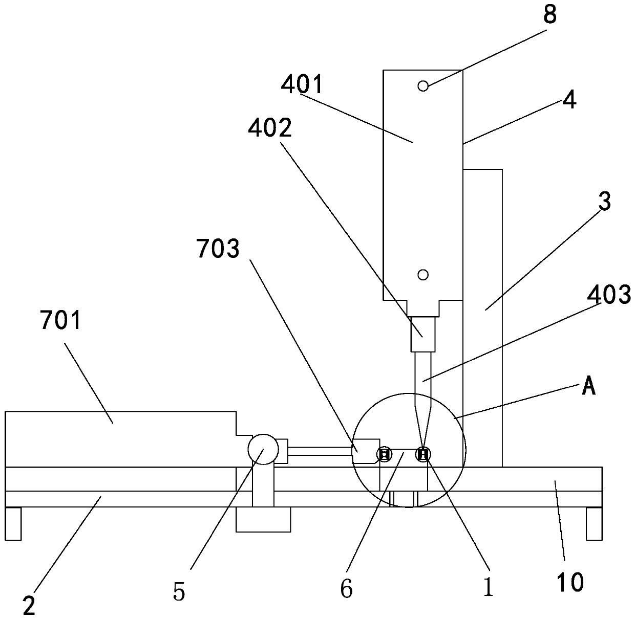
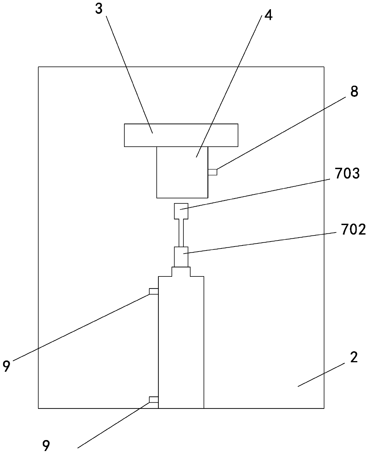
[0035] Such as Figure 1 to Figure 7 As shown, the semi-automatic ball filling device for a cageless full ball bearing includes a cageless full ball bearing 1; the cageless full ball bearing 1 includes an outer ring 101, an inner ring 102 and several steel balls 103, the inner ring 102, An annular cavity 104 filled with steel balls 103 is formed between the outer rings 101, the middle section of the annular cavity 104 is the working position of the steel ball 103 raceway, and the upper section of the annular cavity 104 is the clamping position of the steel ball 103;

[0036] The device also includes a base plate 2, a fixed panel 3, a cylinder system A 4, a manual switch 5, a bearing socket 6, a cylinder system B7 and a foot switch (not shown in the figure), and the manual switch 5 controls the c...


PUM


Abstract

The invention provides a semi-automatic ball filling device for a retainer-free full ball bearing and a ball filling method thereof, and belongs to the technical field of bearing assembly. The semi-automatic ball filling device comprises the retainer-free full ball bearing, a bottom plate, a fixed panel, an air cylinder system A, a manual switch, a bearing sleeve joint seat, an air cylinder systemB and a foot-operated switch, wherein the air cylinder system A comprises an air cylinder A, a piston rod A and a plastic rod A; the air cylinder system B comprises an air cylinder B, a piston rod Band a plastic rod B; when a steel ball is filled, an inner ring is connected to a cylindrical convex head of the bearing sleeve joint in a sleeving mode, the inner wall of the inner ring is in clearance fit with the cylindrical convex head, and an outer ring is arranged outside the inner ring in a sleeving mode; when the manual switch is started, the plastic rod B can extend rightwards to a full ball bearing positioning position under the driving of the air cylinder B, so that the right end surface of the plastic rod B and the left side end of a bearing sleeve joint seat main body are positioned on the same vertical plane; and when the steel ball enters a steel ball clamping position and the foot-operated switch is slightly stepped by a foot, the plastic rod A can downwards press the steelball to a steel ball working position. The semi-automatic ball filling device has the beneficial effect that the labor intensity of workers is reduced.

Description

technical field [0001] The invention relates to a ball filling device and a ball filling method for a full ball bearing without a cage, in particular to a semi-automatic ball filling device and a ball filling method for a full ball bearing without a cage, and belongs to the technical field of bearing assembly equipment and assembly methods thereof. Background technique [0002] The full ball bearing without cage can ensure that the inner ring and the outer ring of the bearing are filled with balls, which increases the bearing capacity of the bearing and avoids the unfavorable situation of large friction surface and serious wear between the steel ball and the cage in the original cage bearing , so that the arrangement of the steel balls in the annular cavity between the inner and outer rings of the bearing maintains a fixed distance, prevents the balls from running away, avoids the mutual grinding between the rolling elements, reduces the movement of the bearing clearance duri...

Claims


Application Information

Patent Timeline
IPC IPC(8): F16C43/06
CPCF16C43/06
Inventor 马松苗
Owner 余姚市新丰轴承有限公司
Learn More