Underground water monitoring and emergency disposal device

An emergency treatment and groundwater technology, which is applied in the direction of general water supply saving, testing water, material inspection products, etc., can solve the problems of high production cost, no emergency measures, water sample mixing, etc., and achieve small footprint, easy maintenance and replacement The effect of convenient parts

Pending Publication Date: 2020-05-19
YIKANG TECH CO LTD
View PDF2 Cites 0 Cited by
  • Summary
  • Abstract
  • Description
  • Claims
  • Application Information

AI Technical Summary

Problems solved by technology

This patent solves the problem of high production cost of monitoring wells in the prior art and poor representativeness of monitoring samples for groundwater sampling at a specific depth, and also solves the problem that only a single depth of groundwater sam

Method used


Image

  • Underground water monitoring and emergency disposal device
  • Underground water monitoring and emergency disposal device
  • Underground water monitoring and emergency disposal device

Examples


Embodiment 1

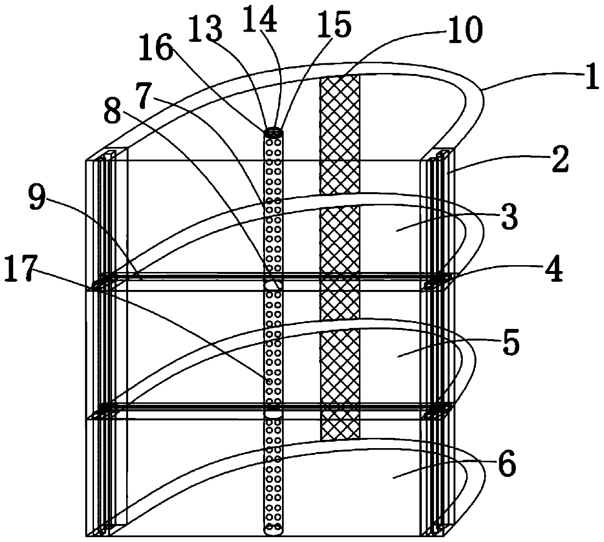
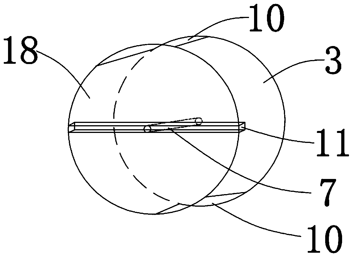
[0022] see Figure 1-4 , in an embodiment of the present invention, a groundwater monitoring and emergency treatment device includes a well body 1, and the well body 1 is composed of a first unit well body 3, a second unit well body 5, and a third unit well body 6, A base 18 is provided below the first unit well body 3, the second unit well body 5, and the third unit well body 6, and a fixing groove 11 is provided on the base 18, and the fixing groove 11 is connected to the lateral support bolt 9 , the lateral support bolt 9 and the fixed bolt 4 are connected by screws, and the front and rear sides of the well body 1 are symmetrically provided with a water-permeable net 10, and the water-permeable net 10 is used for groundwater to enter the well body 1, and at the same time, the medicine passes through the water-permeable net 10 Entering into the underground polluted water body, the left and right sides of the well body 1 are symmetrically provided with supporting grooves 2, w...

Embodiment 2

[0027] The base 18 is connected with the well body 1 with a rubber pad to keep the airtightness of the first unit well body 3, the second unit well body 5 and the third unit well body 6, so as to ensure that the sewage will not leak and affect the monitoring data.

[0028] The follow-up tank 2 is connected with a controllable valve 12, and the controllable valve 12 is fixed on the follow-up tank 2 to control the height of the lateral support bolt 9, and further control the height of the base 18 for extracting groundwater at various stages.

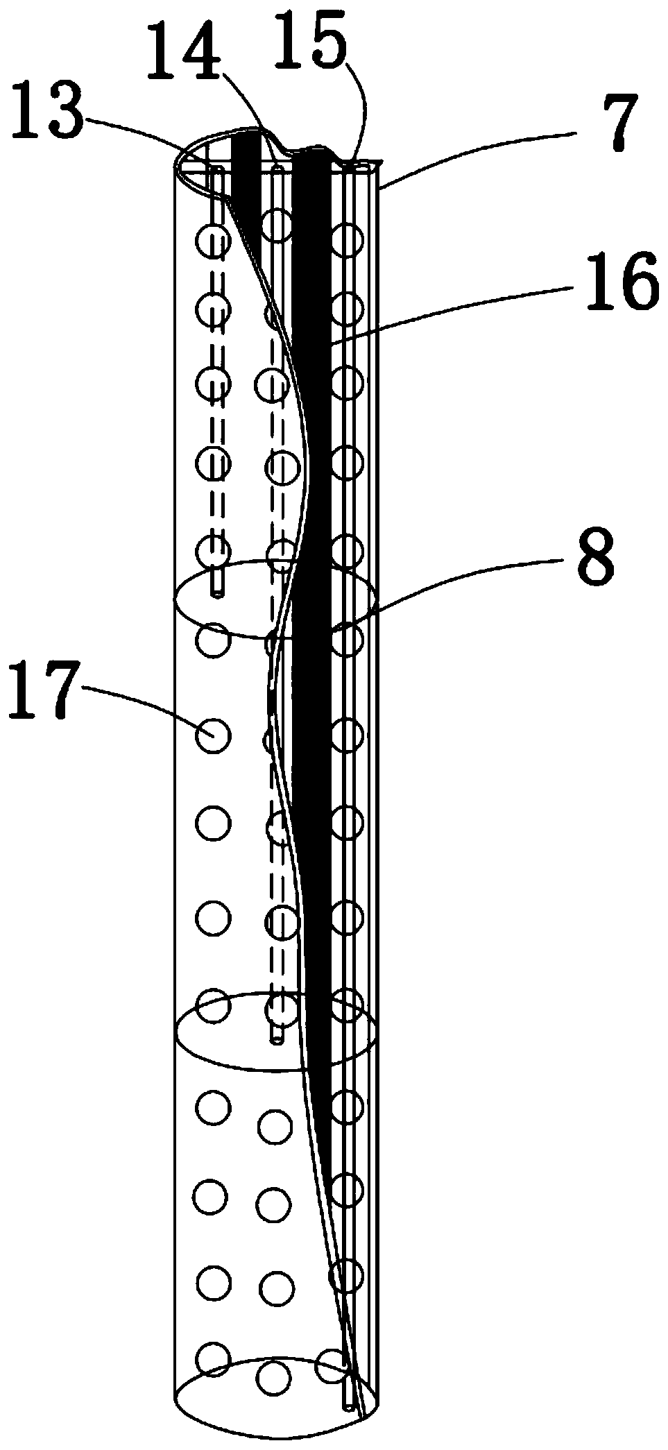
[0029] There are several water inlets 17, which are equidistant and evenly distributed on the outer wall of the pipe body 7, for the entry of groundwater.

[0030] The working principle of the present invention is: when the pollution degree of the overall water level of the groundwater needs to be monitored, the controllable valve 12 is adjusted to adjust the base heights of the first unit well body 3 and the second unit well body 5 to the ...


PUM


Abstract

The invention discloses an underground water monitoring and emergency disposal device. Well body, the well body is composed of a first unit well body, a second unit well body and a third unit well body. Bases are arranged below the first unit well body, the second unit well body and the third unit well body; a fixing groove is formed in the base; the fixing groove is connected with a transverse supporting bolt; the transverse supporting bolt is connected with the fixing bolt through a screw; permeable nets are symmetrically arranged on the front side part and the rear side part of the well body; sequential supporting grooves are symmetrically formed in the left side and the right side of the well body; controllable valves are installed on the two sides of the fixing bolt. The controllablevalve is used for fixing the fixing bolt on the smooth bearing groove; a pipe body is arranged in the center of the well body and provided with a first controllable pipe, a second controllable pipe and a third controllable pipe, the underground water pollution degree of each section can be monitored in real time, a taken water sample has representativeness, emergency treatment can be carried out according to the pollution degree, detection equipment is not prone to blockage, parts are convenient to replace, and the problem that the detection equipment is difficult to treat after blockage is completely eradicated.

Description

technical field [0001] The invention relates to the technical field of groundwater monitoring and emergency treatment, in particular to a groundwater monitoring and emergency treatment device. Background technique [0002] Due to the impact of human activities, groundwater resources have been polluted, causing the water quality of water resources to continue to deteriorate. Coupled with the rapid development of industry and agriculture, and the continuous growth of urban population, the pollution of limited groundwater resources has further deepened. However, groundwater pollution is difficult to observe intuitively, and the monitoring is difficult, and there is a shortage of emergency treatment methods. [0003] In the prior art, the patent CN208334357U describes a groundwater intelligent monitoring well, which includes a cement base embedded in the ground surface, a well pipe fixed in the cement base, and a first-layer protective device and a second-layer protective device...

Claims


Application Information

Patent Timeline
IPC IPC(8): G01N33/18
CPCG01N33/18Y02A20/20
Inventor 杨宏旺曲毅郝进伟丁宇徐慧荟刘雪张华巍王兆选张培杨谢辉李守伟曹贻社于海深常安金田宗康琦李鹏梁春花柳晓明马吉飞牟玉明裴俊玲任国杰杨建成宋晓琳孙国剑王翠辉吴晓峰夏鸿飞刘丽肖洪钢武伟臧岐山张广为张来君赵伟龙李楠郑勇王昌启冯平
Owner YIKANG TECH CO LTD
Why Eureka
Try Eureka