3D visual outsole glue spraying workstation and using method thereof

A workstation, 3D technology, applied in applications, spray devices, clothing, etc., can solve the problems of low use efficiency of glue guns, difficult to remove, and troublesome cleaning process, and achieve novel overall structure, reduce spray volume, and increase area. Effect

Inactive Publication Date: 2020-05-22
福建中泰德玛智能设备有限公司
View PDF0 Cites 6 Cited by
  • Summary
  • Abstract
  • Description
  • Claims
  • Application Information

AI Technical Summary

Problems solved by technology

[0003] Existing glue spray guns are very easy to condense at the small mouth of the glue spray gun during actual use, so that the coagulated colloid needs to be removed every time it is used, and because the glue spray gun The small openings are often small, which makes the cleaning process extremely troublesome, and it is extremely difficult to remove after a long period of working days, which leads to a reduction in the use efficiency of the glue gun. In addition, during the spraying process of the existing glue gun, its spray volume It is fixed and cannot adjust the amount of glue sprayed according to the size of the area to be sprayed during the spraying trajectory, which will easily affect the spraying efficiency and cause waste of glue. In addition, in actual production, sometimes it is necessary to process multiple batches For spraying glue on the outsole of shoes, etc., the glue that needs to be sprayed in each batch may be different. If the glue type requirements are different, you have to stop the machine first to replace the glue gun and glue, which will lead to the need to stop the machine. Replacement, affecting production efficiency

Method used


Image

  • 3D visual outsole glue spraying workstation and using method thereof
  • 3D visual outsole glue spraying workstation and using method thereof
  • 3D visual outsole glue spraying workstation and using method thereof

Examples


Embodiment Construction

[0041] The present invention will be further described below through specific embodiments.

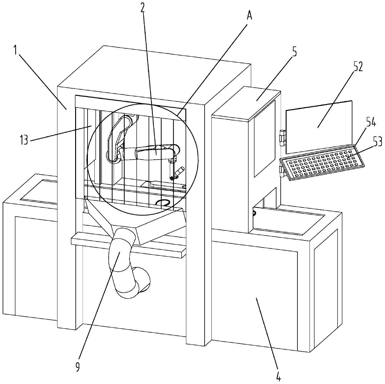
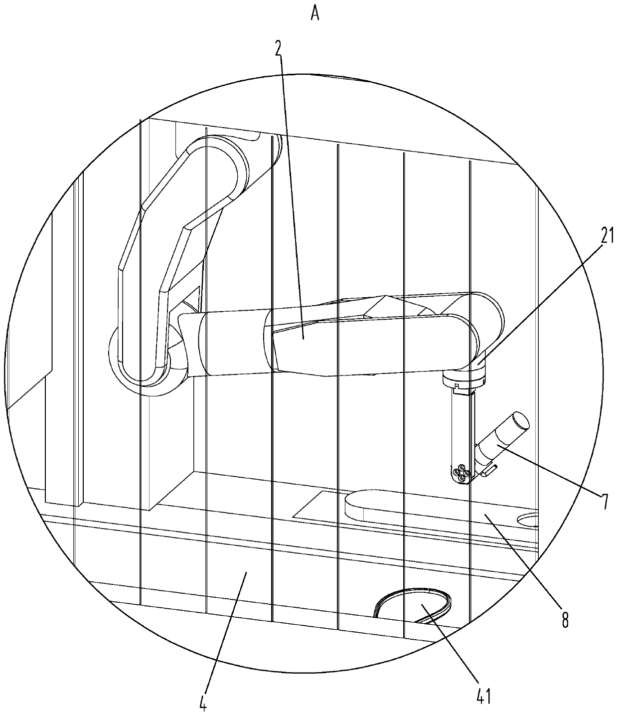
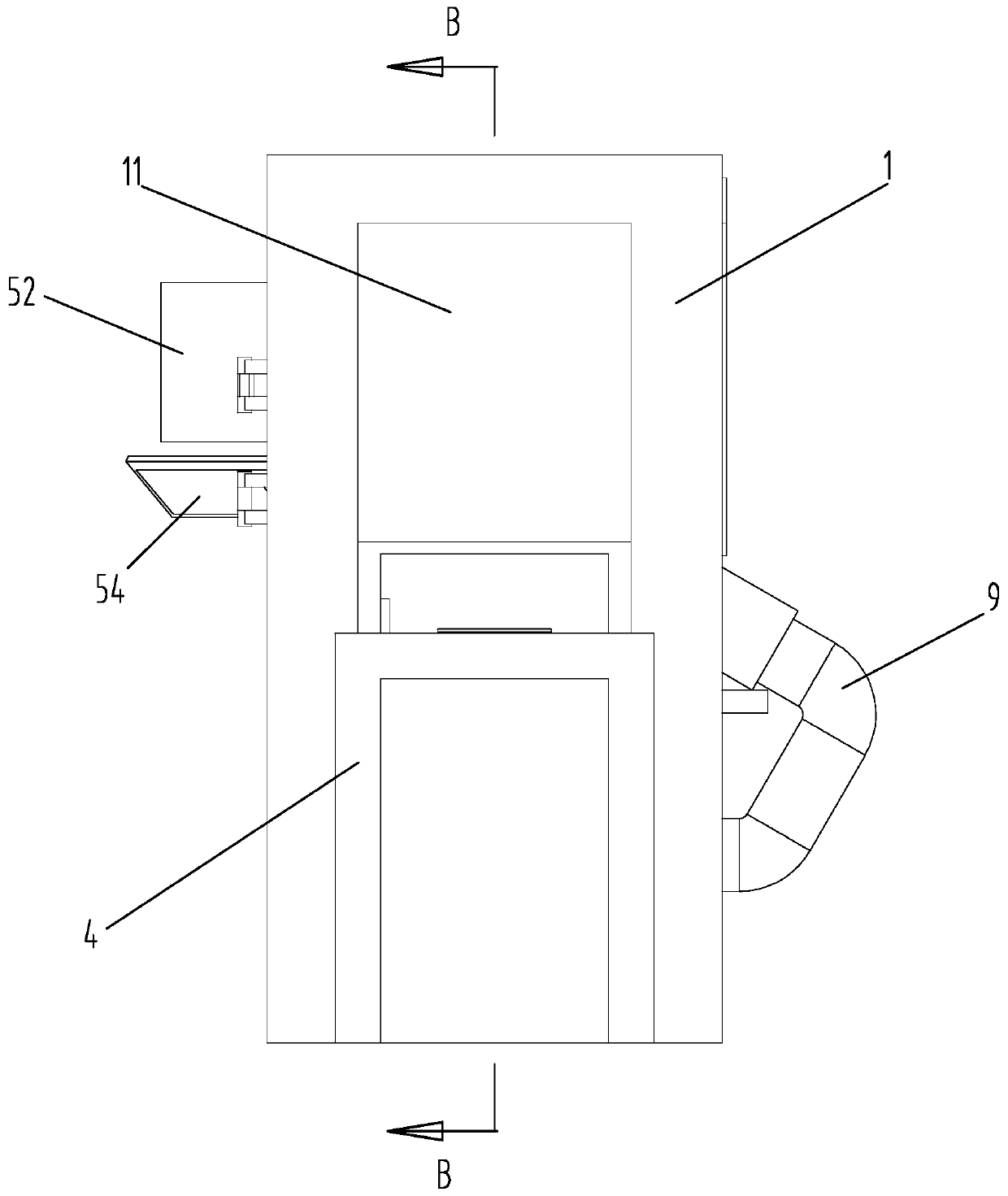
[0042] Such as Figure 1 to Figure 6 As shown, a kind of 3D visual outsole glue spraying workstation according to the present invention is characterized in that it includes a support frame 1, an intelligent manipulator 2, a photoelectric sensor 3, a delivery platform 4, an electric control cabinet 5 and a 3D profile scanner 6, The electric control cabinet 5 is arranged on one side of the support frame 1, and the 3D contour scanner 6 is arranged directly above the feeding end of the conveying platform 4 and installed in the electric control cabinet 5. The electric control cabinet 5. There is a scanning port 51 at the bottom, the photoelectric sensor 3 is fixed on the feeding end of the delivery platform 4, the intelligent manipulator 2 is fixed on the inner top surface of the support frame 1, and the delivery platform 4 is horizontally arranged on the Below the intelligent manipulator ...


PUM


Abstract

The invention relates to the technical field of shoemaking, and particularly relates to a 3D visual outsole glue spraying workstation and a using method thereof. The 3D visual outsole glue spraying workstation is characterized in that the 3D visual outsole glue spraying workstation comprises a support frame, an intelligent manipulator, a photoelectric sensor, a conveying platform, an electric control cabinet and a 3D contour scanner, wherein the electric control cabinet is arranged on one side of the support frame, the 3D contour scanner is arranged right above the feeding end of the conveyingplatform, the photoelectric sensor is fixedly arranged at the feeding end of the conveying platform, the intelligent manipulator is arranged on the inner top surface of the support frame, the conveying platform is horizontally arranged below the intelligent manipulator, a glue spraying gun is arranged on the claw seat at the tail end of the intelligent manipulator,a plurality of glue outlet smallopenings for spraying glue independently are formed in the glue spraying gun, and a cleaning device for cleaning the head of the glue spraying gun is arranged on one side of the support frame. According to the 3D visual outsole glue spraying workstation and the using method thereof, the overall structure is novel, the head of the glue spraying gun can be cleaned in time, and the spraying amount of glue is conveniently controlled; and in addition, the effect of spraying different types of glue can also be achieved.

Description

technical field [0001] The invention relates to the technical field of shoemaking, in particular to a 3D visual outsole glue spraying workstation and a method for using the same. Background technique [0002] In the shoemaking process, the quality of the sizing operation has always been an important factor in determining the quality of shoes. With the improvement of automation in the shoemaking industry, the sizing operation of shoemaking is gradually being replaced by automatic equipment. Using automated equipment to carry out shoe sizing work, the working method is mainly divided into two types: sizing track matching generation and online automatic generation according to the different sizing track generation methods. The former uses features to match and call existing sizing Track, due to the diversification of shoe styles and materials, it is time-consuming and energy-consuming to adopt this method; the latter automatically generates sizing tracks through online measure...

Claims


Application Information

Patent Timeline
Patent Type & Authority Applications(China)
IPC IPC(8): B05B13/04B05B15/50B05B14/00B05B12/00B05B12/12B05B15/55A43D25/18
CPCA43D25/183B05B12/00B05B12/122B05B13/0431B05B14/00B05B15/50B05B15/557
Inventor 许雄生
Owner 福建中泰德玛智能设备有限公司
Why Eureka
Try Eureka