Cable winding device for electric power maintenance

A winding device and electric power maintenance technology, which is applied in the directions of transportation and packaging, delivery of filamentous materials, thin material processing, etc., can solve the problems of unable to bundle cables, increase the workload of electric workers, bending deformation, etc., and meet the requirements of cable Length requirements, easy to bundle and organize, and improve the effect of service life

Inactive Publication Date: 2020-05-22
新沂市高新科技产业园运营管理有限公司
View PDF0 Cites 0 Cited by
  • Summary
  • Abstract
  • Description
  • Claims
  • Application Information

AI Technical Summary

Problems solved by technology

The structural size of this type of product is usually small and uniform, and the manufacturing precision is high. The cable has the characteristics of internal energization and external insulation. With large current (tens of amps to thousands of amps) and high voltage (220V to 500kV and above), when erecting a new cable rack, it is often necessary to carry more cables to avoid emergencies. Traditional cable winding and storage , The bundling is all done by workers, which increases the workload of electric workers, and the number of meters manually is not accurate enough to accurately bundle the remaining cables according to different customer needs, resulting in rework at the factory, wasting time, and increasing costs. With a certain weight, the small winding devices on the market have poor stability and are prone to bending deformation

Method used


Image

  • Cable winding device for electric power maintenance
  • Cable winding device for electric power maintenance
  • Cable winding device for electric power maintenance

Examples


Embodiment Construction

[0014] The technical solutions in the embodiments of the present invention will be clearly and completely described below in conjunction with the accompanying drawings in the embodiments of the present invention. Obviously, the described embodiments are only a part of the embodiments of the present invention, rather than all the embodiments. Based on the embodiments of the present invention, all other embodiments obtained by those of ordinary skill in the art without creative work shall fall within the protection scope of the present invention.

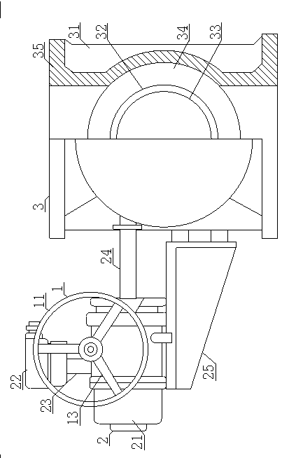
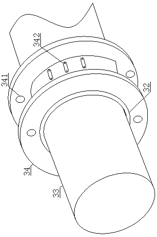
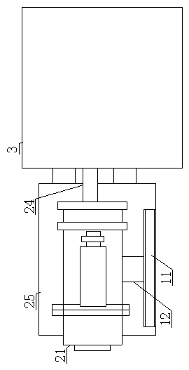
[0015] See Figure 1-3 , A cable winding device for power maintenance, comprising a winding mechanism 1, a driving mechanism 2 and a winding mechanism 3. The winding mechanism 1 is connected to the driving mechanism 2, and the winding mechanism 3 is located on one side of the winding mechanism 1. The winding mechanism 1 includes a winding ring 11, a power shaft 12, and a connecting rod 13. A power shaft 12 is installed in the middle of t...


PUM


Abstract

The invention discloses a cable winding device for electric power maintenance. A winding mechanism, a drive mechanism and a wire collecting mechanism are included. The winding mechanism is connected with the drive mechanism. A power shaft is arranged at the middle portion of a winding ring. The winding ring and the power shaft are fixedly connected through connecting rods. Through the arrangementof the winding ring, the cable dredging function is achieved. The connecting rod combined manner is a triangular combination, stability of the winding ring is improved, and the compression deformationphenomenon caused by a too heavy cable is avoided. The cable is fixed to a cable head fixing clamp, a runner back plate fixes the winding cable, and cable loosening is avoided. The runner back plateis provided with knotting holes, a bundling rope penetrates through the knotting holes, cable bundle-by-bundle tidying is convenient, and time is saved. When a runner starts to rotate, the cable is twisted on the runner back plate. The device is high in stability, time and labor are saved, the winding meters can be freely set, and the workload of workers is reduced.

Description

Technical field [0001] The invention relates to the technical field of cable winding, in particular to a cable winding device for power maintenance. Background technique [0002] A cable is usually a rope-like cable formed by twisting several or several groups of wires (at least two in each group). Each group of wires is insulated from each other and is often twisted around a center. The whole outer bread has a height Insulating coating. With the rapid development of the communications industry in the past two decades, products have also developed at an astonishing speed. From the simple telephone and telegraph cables in the past to thousands of pairs of telephone cables, coaxial cables, optical cables, Data cables and even combined communication cables. The structural size of this type of product is usually small and uniform, and the manufacturing accuracy is high. The cable has the characteristics of internal energization and external insulation. Power cables are mainly used f...

Claims


Application Information

Patent Timeline
Patent Type & Authority Applications(China)
IPC IPC(8): B65H61/00B65H57/06B65H75/28
CPCB65H57/06B65H61/00B65H75/28B65H2701/34
Inventor 魏加珍
Owner 新沂市高新科技产业园运营管理有限公司
Why Eureka
Try Eureka