Turbulence prevention and scale reduction structure and optical liquid concentration test device

A liquid concentration and protective device technology, applied in the field of sensors, can solve the problems of low reliability, inaccurate measurement, and low accuracy of urea liquid concentration measurement results, and achieve the effect of guaranteeing life

Pending Publication Date: 2017-08-18
DONGGUAN ZHENGYANG ELECTRONICS MECHANICAL CO LTD
View PDF8 Cites 0 Cited by
  • Summary
  • Abstract
  • Description
  • Claims
  • Application Information

AI Technical Summary

Problems solved by technology

[0015] Although the above-mentioned sensor for measuring liquid concentration can measure urea concentration, this device cannot eliminate factors that affect measurement accuracy and stability during the measurement process, for example, turbulent flow during the measurement process and impact due to turbulent flow, added liquid, etc. The air bubbles brought by it; the scale formed by the long-term settlement of the liquid on the exit surface and the entrance surface
Because the bubbles will directly affect the direction of the light path and the scattering of light, and the formation of scale will cause the formation of a halo when the light exits to the end point, and both scattering and halo will cause inaccurate measurement
In this way, the urea solution concentration measurement result obtained by the above scheme has low precision and low reliability

Method used


Image

  • Turbulence prevention and scale reduction structure and optical liquid concentration test device
  • Turbulence prevention and scale reduction structure and optical liquid concentration test device
  • Turbulence prevention and scale reduction structure and optical liquid concentration test device

Examples


Embodiment 1

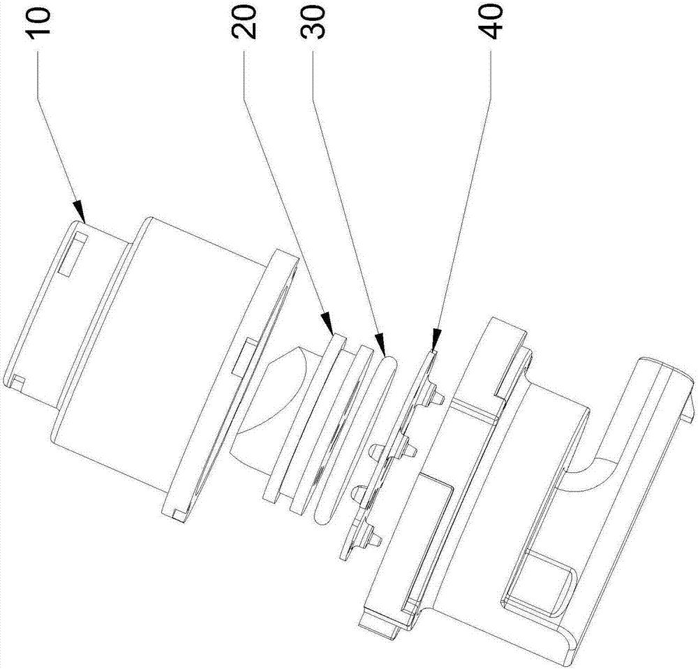
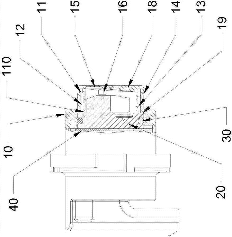
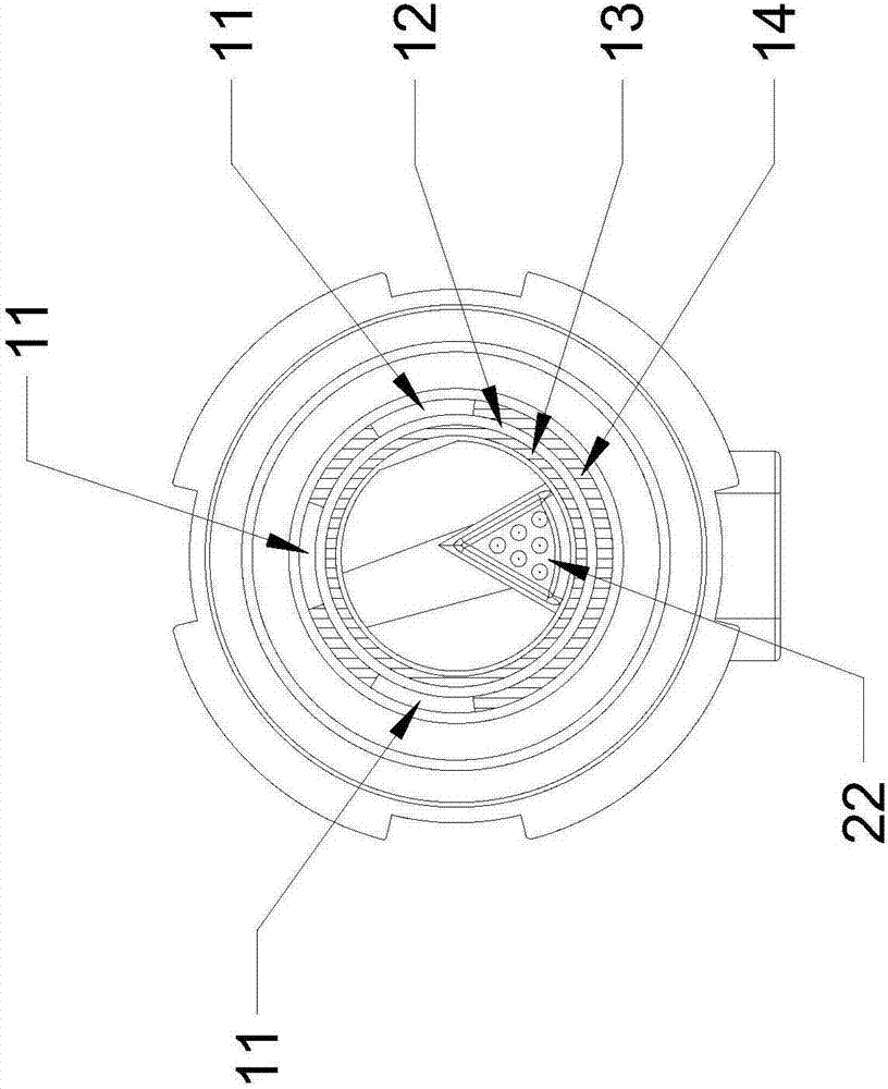
[0092] Such as Figure 1 to Figure 3 As shown, an optical liquid concentration sensor includes a turbulence shield 10 , an optical component 20 of a sensor device, a sealing ring 30 , and an assembly bracket 40 . The turbulence shield 10 is connected to the assembly bracket 40 through fasteners. The optical component 20 is locked by the assembly bracket through the annular platform 19 of the outer ring column 14 and the limiting platform 25 of the optical component in the turbulence shield 10 .

[0093] The turbulent flow shield 10 is designed as an integrated engineering plastic part, and its liquid inlet 11 and ring post gap 12 are molded at one time. Specifically, the liquid inlet 11 is designed at the end far away from the tested liquid testing area of ​​the sensor. The above-mentioned optical component 20 and the turbulence shield 10 are locked by fasteners. After locking, the inner ring column 13 of the turbulence shield and the limiting platform 25 of the optical comp...

Embodiment 2

[0099] Such as Figure 1 to Figure 3 As shown, an optical liquid concentration sensor includes a turbulence shield 10 , an optical component 20 of a sensor device, a sealing ring 30 , and an assembly bracket 40 . The turbulence shield 10 is connected to the assembly bracket 40 through fasteners. The optical component 20 is locked by the assembly bracket through the annular platform 19 of the outer ring column 14 and the limiting platform 25 of the optical component 20 in the turbulence shield 10 .

[0100] The turbulent flow shield 10 is designed as an integrated engineering plastic part, and its liquid inlet 11 and ring post gap 12 are molded at one time. Specifically, the liquid inlet 11 is designed at the end far away from the tested liquid testing area of ​​the sensor. The above-mentioned optical component 20 and the turbulence shield 10 are locked by fasteners. After locking, the inner ring column 13 of the turbulence shield and the limiting platform 25 of the optical c...

Embodiment 3

[0106] Such as Figure 1 to Figure 3 As shown, an optical liquid concentration sensor includes a turbulence shield 10 , an optical component 20 of a sensor device, a sealing ring 30 , and an assembly bracket 40 . The turbulence shield 10 is connected to the assembly bracket 40 through fasteners. The optical component 20 is locked by the assembly bracket through the annular platform 19 of the outer ring column 14 and the limiting platform 25 of the optical component 20 in the turbulence shield 10 .

[0107] The turbulent flow shield 10 is designed as an integrated engineering plastic part, and its liquid inlet 11 and ring post gap 12 are molded at one time. Specifically, the liquid inlet 11 is designed at the end far away from the tested liquid testing area of ​​the sensor. The above-mentioned optical component 20 and the turbulence shield 10 are locked by fasteners. After locking, the inner ring column 13 of the turbulence shield and the limiting platform 25 of the optical c...


PUM


Abstract

The invention discloses a turbulence prevention device and scale reduction device for an optical liquid concentration sensor. The turbulence prevention device and scale reduction device comprise an outer column ring, an inner column ring, a head cover, an incident plane, a reflecting surface and an emergent surface. The invention further discloses an optical liquid concentration test device comprising the turbulence prevention device and the scale reduction device. Through providing a relatively static environment, bubbles in a tested solution can be reduced, dredged and released to the maximum extent, and the test reliability is improved. According to a scale reduction structure of an optical component of the optical liquid concentration sensor device, scales on the emergent surface and the incident plane of the sensor caused by long-term use, impurity precipitation and electrostatic interaction are guided and deposition of the scales on the effective area parts of the emergent surface and the incident plane is delayed as far as possible, so that halo formation is avoided and the detection accuracy of the sensor is improved. In addition, through providing the optical liquid concentration test device, a main body of the sensor is effectively protected, the service life is prolonged, and meanwhile, the accuracy is improved.

Description

technical field [0001] The present invention relates to the technical field of sensors, in particular to a sensor device for a sensor, a turbulence protection device, a structure for reducing scale formation in the sensor device, and a sensor testing device, and further relates to a sensor device for a liquid concentration sensor, a turbulence protection device and The structure for reducing scale formation in the sensor device and the test device for the liquid concentration quality sensor further relate to a sensor device for an optical liquid concentration sensor, a turbulent flow protection device, a structure for reducing the scale formation in the sensor device, and a test device for the optical liquid concentration quality sensor. [0002] technical background [0003] Diesel engines have been widely used in all walks of life with higher horsepower. Compared with gasoline engines, the high temperature of diesel in the cylinder results in higher formation and emission o...

Claims


Application Information

Patent Timeline
Patent Type & Authority Applications(China)
IPC IPC(8): G01N21/01
CPCG01N21/01G01N2021/0112
Inventor 不公告发明人
Owner DONGGUAN ZHENGYANG ELECTRONICS MECHANICAL CO LTD
Why Eureka
Try Eureka