Microbial fermentation feeding and stirring device

A microbial fermentation and stirring device technology, applied in the direction of enzymology/microbiology device, biochemical cleaning device, bioreactor/fermentation tank combination, etc., can solve the problems of unfavorable precipitation, unfavorable uniform stirring, small stirring range, etc. Achieve the effect of increasing the stirring area, avoiding agglomeration and increasing friction

Inactive Publication Date: 2020-05-22
JIANGSU UNISON BIOTECH DEV
0 Cites 0 Cited by

AI-Extracted Technical Summary

Problems solved by technology

[0003] In order to avoid its agglomeration during microbial fermentation, it is necessary to use a stirring device to stir it. At present, the production equipment uses a flat disc worm wheel agitator, ...

Method used

Please refer to Fig. 1-3, a kind of microbial fermentation beats stirring device, comprises fermenter 1, the both sides of fermenter 1 bottom are all fixedly equipped with support leg 2, and the bottom of support leg 2 is bonded by adhesive Anti-skid pad 19 is arranged, and the bottom of anti-skid pad 19 is provided with anti-skid pattern, by the setting of anti-skid pad 19, the frictional force at the bottom of support leg 2 has been increased, the situation that rocking occurs in support leg 2 when avoiding this mixing device to use, has improved The stability of support leg 2 when this mixing device is used, the bottom of fermenting case 1 is communicated with discharge port 3, and the left side of fermenting case 1 is fixedly installed with housing 4, and the bottom of housing 4 is provided with heat dissipation port 20, and heat dissipation The number of openings 20 is not less than five, and the setting of the heat dissipation openings 20 can protect the positive and negative motors 5, avoiding the positive and negative motors caused by the excessive temperature in the housing 4 when the positive and negative motors 5 are in use. The damaged condition of the motor 5 prolongs the service life of the positive and negative motor 5. The positive and negative motor 5 is fixedly installed on the left side of the fermentation box 1 and inside the housing 4, and the bearing 6 is fixedly installed on the right side of the inner cavity of the fermentation box 1. , the output end of the positive and negative motor 5 is fixedly equipped with a screw 7, the right side of the screw 7 penetrates to the inner cavity of the fermentation tank 1 an...

Abstract

The invention discloses a microbial fermentation feeding and stirring device. The device comprises a fermentation tank, wherein supporting legs are fixedly arranged on two sides of the bottom of the fermentation tank; a discharge opening is communicated with the bottom of the fermentation tank; a shell is fixedly arranged on the left side of the fermentation tank; a forward and reverse motor is fixedly arranged on the left side of the fermentation tank and is positioned inside the shell; and a bearing is fixedly arranged on the right side of the cavity of the fermentation tank. The microbial fermentation feeding and stirring device can solve the problems that an existing stirring device has low stirring efficiency and cannot perform uniform stirring through cooperation of the forward and reverse motor, the bearing, a screw rod, a slide rail, a motor, an assembly block, a fixed rod, a slide block, a stirring shaft, a stirring blade, a screw tube, a control valve and a controller, and can increase the stirring area of the stirring blade when being used, so that the situation that raw materials at corners cannot be timely stirred and are caked can be avoided, precipitate separation can be favored, the fermentation progress can be accelerated, and the practicality of the stirring device can be improved.

Application Domain

Technology Topic

Image

  • Microbial fermentation feeding and stirring device
  • Microbial fermentation feeding and stirring device
  • Microbial fermentation feeding and stirring device

Examples

  • Experimental program(1)

Example Embodiment

[0021] The technical solutions in the embodiments of the present invention will be clearly and completely described below in conjunction with the accompanying drawings in the embodiments of the present invention. Obviously, the described embodiments are only a part of the embodiments of the present invention, rather than all the embodiments. Based on the embodiments of the present invention, all other embodiments obtained by those of ordinary skill in the art without creative work shall fall within the protection scope of the present invention.
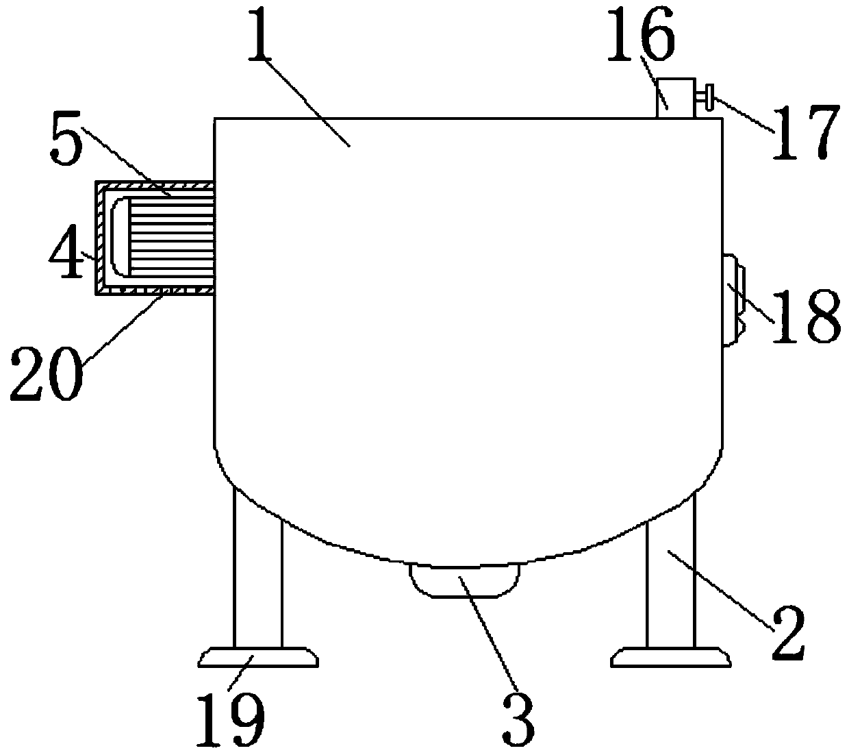
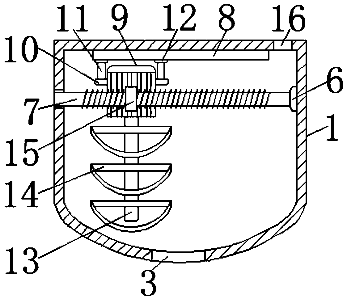
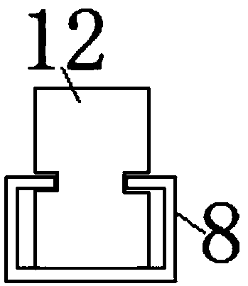
[0022] See Figure 1-3 , A microbial fermentation stirring device, including a fermentation tank 1, both sides of the bottom of the fermentation tank 1 are fixedly installed with support legs 2, and the bottom of the support legs 2 is bonded with a non-slip pad 19 through an adhesive, and the non-slip pad 19 There are anti-slip patterns on the bottom of the anti-skid pad 19, which increases the friction at the bottom of the support leg 2, avoids the shaking of the support leg 2 when the stirring device is used, and improves the support leg 2 when the stirring device is used. Stability, the bottom of the fermentation tank 1 is connected with a discharge port 3, the left side of the fermentation tank 1 is fixedly installed with a shell 4, the bottom of the shell 4 is provided with a heat dissipation port 20, and the number of heat dissipation ports 20 is not less than five , Through the setting of the heat sink 20, the positive and negative motors 5 can be protected, avoiding the damage of the positive and negative motors 5 due to the high temperature in the housing 4 when the positive and negative motors 5 are in use. The service life of the anti-motor 5, the left side of the fermentation tank 1 and the inside of the housing 4 are fixedly installed with a positive and negative motor 5, the right side of the inner cavity of the fermentation tank 1 is fixedly installed with a bearing 6, and the output end of the positive and negative motor 5 is fixed A screw 7 is installed. The right side of the screw 7 penetrates into the inner cavity of the fermentation tank 1 and is sleeved with the inner side of the bearing 6. The left side of the fermentation tank 1 is provided with a through hole for use with the screw 7, and the inner cavity of the fermentation tank 1 A slide rail 8 is fixedly installed on the top. The slide rail 8 is a linear guide rail. The inner wall of the slide rail 8 is slidably connected to the slider 12. The setting of the slider 12 and the slide rail 8 can limit the motor 9 while reducing The friction between the motor 9 and the fermentation tank 1 is reduced, so that the motor 9 slides more smoothly. The inner cavity of the fermentation tank 1 is provided with a motor 9, and the surface of the motor 9 is fixedly installed with a mounting block 10 and the top of the mounting block 10 A fixed rod 11 is fixedly installed, the top of the fixed rod 11 is fixedly installed with a slider 12, the output end of the motor 9 is fixedly installed with a stirring shaft 13, the surface of the stirring shaft 13 is sleeved with a stirring blade 14, and the surface of the screw 7 is threaded The solenoid 15, the surface of the solenoid 15 is fixedly connected with the motor 9. The right side of the top of the fermentation tank 1 is connected with a feed port 16, the surface of the feed port 16 is installed with a control valve 17, and the right side of the fermentation tank 1 is provided with a control The model of the controller 18 is MAM-220, the left side of the controller 18 is screwed with the fermentation tank 1 through bolts, the model of the positive and negative motor 5 is BM8024-8024-B, and the model of the motor 9 is HEM-34D2802- 03IP.
[0023] When in use, the user first operates the controller 18 so that the controller 18 controls the motor 9 and the forward and reverse motor 5 to work, so that the motor 9 drives the stirring shaft 13 to rotate, and the stirring blade 14 is driven by the stirring shaft 13 to stir the raw materials. The raw materials are agglomerated during the fermentation process. At the same time, the positive and negative motor 5 drives the screw 7 to rotate through the cooperation of the through hole and the bearing 6, so that the screw 7 drives the solenoid 15 to move left and right, and the solenoid 15 passes through the slider 12 and the slide rail. 8. The cooperation of the fixed rod 11 and the mounting block 10 drives the motor 9 to move left and right, so that the motor 9 drives the stirring blade 14 to move left and right through the cooperation of the stirring shaft 13, thereby increasing the stirring area of ​​the stirring blade 14 and achieving the stirring of the stirring device The advantages of more uniformity and high mixing efficiency.
[0024] To sum up, the microbial fermentation stirring and stirring device, through the positive and negative motor 5, bearing 6, screw 7, slide rail 8, motor 9, mounting block 10, fixed rod 11, sliding block 12, stirring shaft 13, stirring blade 14. The mutual cooperation of the solenoid 15, the control valve 17 and the controller 18 solves the problems of low mixing efficiency and inability of uniform mixing of existing mixing devices.

PUM

no PUM

Description & Claims & Application Information

We can also present the details of the Description, Claims and Application information to help users get a comprehensive understanding of the technical details of the patent, such as background art, summary of invention, brief description of drawings, description of embodiments, and other original content. On the other hand, users can also determine the specific scope of protection of the technology through the list of claims; as well as understand the changes in the life cycle of the technology with the presentation of the patent timeline. Login to view more.

Similar technology patents

Solid wood board leftover material pulping device and using method thereof

InactiveCN111676721AIncrease the mixing areaImprove pulping efficiencyWood working apparatusGrain treatmentsProcess engineeringSolid wood
Owner:安徽省汇金木业股份有限公司

Wall-mounted type air-conditioner indoor unit

PendingCN110553313AIncrease the mixing areaEvenly mixed airLighting and heating apparatusAir conditioning systemsIndoor airEvaporator
Owner:QINGDAO HAIER AIR CONDITIONER GENERAL CORP LTD

Classification and recommendation of technical efficacy words

  • Increase the mixing area
  • Avoid caking

Reaction kettle for preparation of electrolyte of lithium battery

InactiveCN108654543AExpand the scope of work activitiesIncrease the mixing areaShaking/oscillating/vibrating mixersRotary stirring mixersEngineeringElectrolyte
Owner:DATONG XINCHENG NEW MATERIAL CO LTD

Domestic noodle maker

InactiveCN104026182AIncrease the mixing areaEnhance stirringDough extruding machinesBiochemical engineering
Owner:浙江志美电器有限公司

Down feather cleaning machine capable of preventing block formation during down feather cleaning

ActiveCN106498505AAvoid cakingSpeed up cleaningWool fibre washing/scouringEngineeringMechanical engineering
Owner:无锡锡东新农村投资发展有限公司

Intermittent fluidization thermal energy and chemical energy storage and release reaction device and working method

ActiveCN105841537AMake up for inhomogeneitiesAvoid cakingHeat storage plantsFluidised bed heat exchangersChemical energyEngineering
Owner:SOUTH CHINA UNIV OF TECH

Instant chelated solid water-soluble fertilizer and preparation method thereof

InactiveCN107586209AAvoid cakingGood instant solubilityFertilizer mixturesNutrientChemistry
Owner:成都云图控股股份有限公司
Why Eureka
Try Eureka