Magnetic levitation track beam post-cast section steel bar and sleeve connecting structure and connecting process

A steel sleeve and connection structure technology, which is applied in the direction of track, track laying, track maintenance, etc., can solve the problems of easy pollution, inconvenient transportation, poor apparent quality of concrete, etc.

Inactive Publication Date: 2020-05-22
CHINA MCC5 GROUP CORP
View PDF0 Cites 1 Cited by
  • Summary
  • Abstract
  • Description
  • Claims
  • Application Information

AI Technical Summary

Problems solved by technology

This connection method has the following disadvantages: 1. The apparent quality of the concrete is poor before the concrete is poured on the rough surface of the connection.
2. The post-casting section of the prefabricate

Method used


Image

  • Magnetic levitation track beam post-cast section steel bar and sleeve connecting structure and connecting process
  • Magnetic levitation track beam post-cast section steel bar and sleeve connecting structure and connecting process

Examples


Embodiment 1

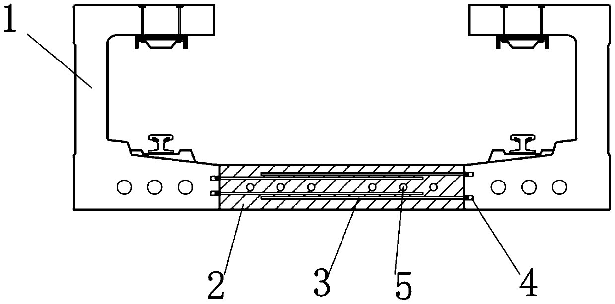
[0024] Such as figure 1 , figure 2 As shown, in this embodiment, a kind of steel sleeve connection structure of the post-casting section of the magnetic levitation track beam is arranged between two track beams 1, including several sleeves 4 arranged on the inner side surface of the bottom of the track beam 1 and arranged The steel bar 3 in the sleeve 4, the length of the steel bar 3 is less than the distance between the track beam 1 and the track beam 1 and greater than half of the distance between the track beam 1 and the track beam 1, between the track beam 1 and the bottom of the track beam 1 Pouring with concrete layer 2.

[0025] After the track beam 1 is prefabricated in this solution, it is convenient to transport because there is no pre-embedded steel bar at the joint of the track beam 1, which can effectively reduce the transportation cost of the track beam 1 and transport the prefabricated track beam 1 to the construction site. Install the steel bars 3 in the sle...

Embodiment 2

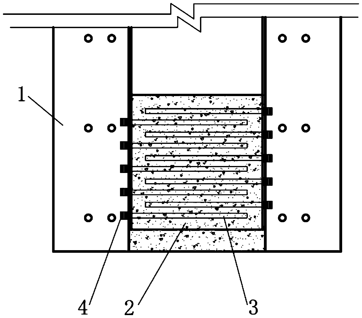
[0028] On the basis of the above embodiments, in this embodiment, the sleeves 4 on the two track beams 1 are arranged at equal intervals and staggered along the length direction of the track beams 1 .

[0029] The sleeves 4 are arranged in a staggered manner, so that the steel bars 3 installed on the two steel bars 3 can avoid each other, so that the steel bars 3 can be kept straight without interference, and it is beneficial to evenly distribute the steel bars 3, so that the concrete layer 2 formed by pouring can be placed everywhere. The intensity remains the same.

[0030] In this embodiment, the track beam 1 is provided with two layers of sleeves 4 along the height direction of the track beam 1 .

[0031] In this way, the density of steel bars in the concrete layer 2 can be increased to enhance the strength of the concrete layer 2 and increase the connection strength of the two track beams 1 . According to the thickness of the joint, three or more layers of sleeves 4 can ...

Embodiment 3

[0034] On the basis of the above embodiments, in this embodiment, the steel bars 3 are provided with threads, and the sleeve 4 is provided with internal threads for use with the steel bars 3 . In this way, the steel bar 3 and the sleeve 4 can be screwed together to enhance the connection strength between the steel bar 3 and the sleeve 4 .

[0035] In this embodiment, adjacent steel bars 3 are bound to each other. In this way, the reinforcement bars 3 can be connected to each other, thereby improving the strength of the concrete layer 2 .


PUM


Abstract

The invention discloses a magnetic levitation track beam post-cast section steel bar and sleeve connecting structure and a connecting process. The connecting structure is arranged between two track beams and comprises a plurality of sleeves arranged on the inner side faces of the bottoms of the track beams and steel bars arranged in the sleeves, the length of the steel bars is smaller than the distance between the track beams and larger than one half of the distance between the track beams, and a concrete layer is poured between the bottoms of the track beams. The beneficial effects of the invention are that: according to the scheme, steel bars do not need to be pre-buried at the connecting position of the prefabricated track beams, the track beam prefabricating efficiency can be improved,the production period of the track beams is shortened, the track beams are convenient to transport, the transport cost is reduced, steel bar positioning, straightening and other work do not need to be conducted in the later period, and the surfaces of the track beams cannot be damaged.

Description

technical field [0001] The invention relates to the field of magnetic levitation track construction, in particular to a steel bar sleeve connection structure and a connection process of a post-casting section of a magnetic levitation track beam. Background technique [0002] At present, in most post-cast section beams and slab concrete in my country, pre-embedded steel bars are often used to reinforce the pre-embedded steel bars at the joints, and the excess concrete at the joints is excavated during the connection to expose part of the steel bars. After the steel bars are straightened, they are staggered one by one, bound or welded with steel bars of the same specification, and poured concrete for maintenance. This connection method has following several deficiencies: 1, the concrete appearance quality is poor before the concrete pouring on the chisel rough surface at the connection. 2. The post-casting section of the prefabricated slab is inconvenient for transportation du...

Claims


Application Information

Patent Timeline
IPC IPC(8): E01B25/30E01B29/00
CPCE01B25/305E01B29/00
Inventor 杨根明罗利胡云洁陈艳
Owner CHINA MCC5 GROUP CORP
Why Eureka
Try Eureka