Integrated cooking utensil and control method thereof

A technology of cooking utensils and concentration sensors, which is applied in the field of kitchen appliances, can solve the problems of destroying the public flue, oil fume backflow, fast flow speed, etc., to reduce the flow speed of oil fume, maintain indoor pressure balance, and improve the effect of adsorption and filtration

Active Publication Date: 2020-05-22
NINGBO FOTILE KITCHEN WARE CO LTD
View PDF10 Cites 9 Cited by
  • Summary
  • Abstract
  • Description
  • Claims
  • Application Information

AI Technical Summary

Problems solved by technology

[0004] The existing technology has the following problems: 1. The outlet connection needs to destroy the public flue: install an integrated stove upstairs, and open a hole under the flue. The distance is relatively close. During use, the upper floor will affect the smoke exhaust downstairs, the check valve will be sucked open, or the oil fume from downstairs will flow back to the smoke exhaust outlet upstairs, and the user experience of odor backflow is not good; There are many different cooking methods such as frying, frying, steaming, and boiling. In the case of a large amount of smoke, the amount of oil fume escape is relatively large, which cannot meet the cooking needs of different consumers; 3. There is no oil fume purification treatment facility inside the range hood, The internal cleaning and maintenance of the machine need to disassemble other appliances, which is inconvenient for cleaning and maintenance; 4. The operation of integrated cooking appliances is relatively simple, lacking intelligence and interconnection
[0005] In addition, because the air inlet of ordinary integrated cooking appliances is relatively close to the pot surface, and the flow velocity is relatively fast, oil fume pollutants in the entire flow channel in the appliance will quickly and easily concentrate at the bottom of the air channel to contaminate the electronic control devices, which poses a greater risk

Method used


Image

  • Integrated cooking utensil and control method thereof
  • Integrated cooking utensil and control method thereof
  • Integrated cooking utensil and control method thereof

Examples


Embodiment Construction

[0035] Embodiments of the present invention are described in detail below, examples of which are shown in the drawings, wherein the same or similar reference numerals denote the same or similar elements or elements having the same or similar functions.

[0036]In describing the present invention, it should be understood that the terms "center", "longitudinal", "transverse", "length", "width", "thickness", "upper", "lower", "front", " Back", "Left", "Right", "Vertical", "Horizontal", "Top", "Bottom", "Inner", "Outer", "Clockwise", "Counterclockwise", "Axial", The orientation or positional relationship indicated by "radial", "circumferential", etc. is based on the orientation or positional relationship shown in the drawings, and is only for the convenience of describing the present invention and simplifying the description, rather than indicating or implying the referred device or element must have a particular orientation, be constructed, and operate in a particular orientation...


PUM


Abstract

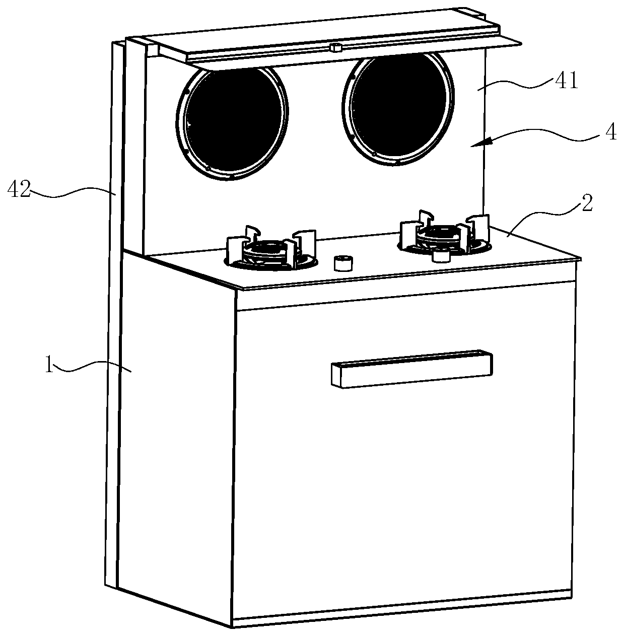
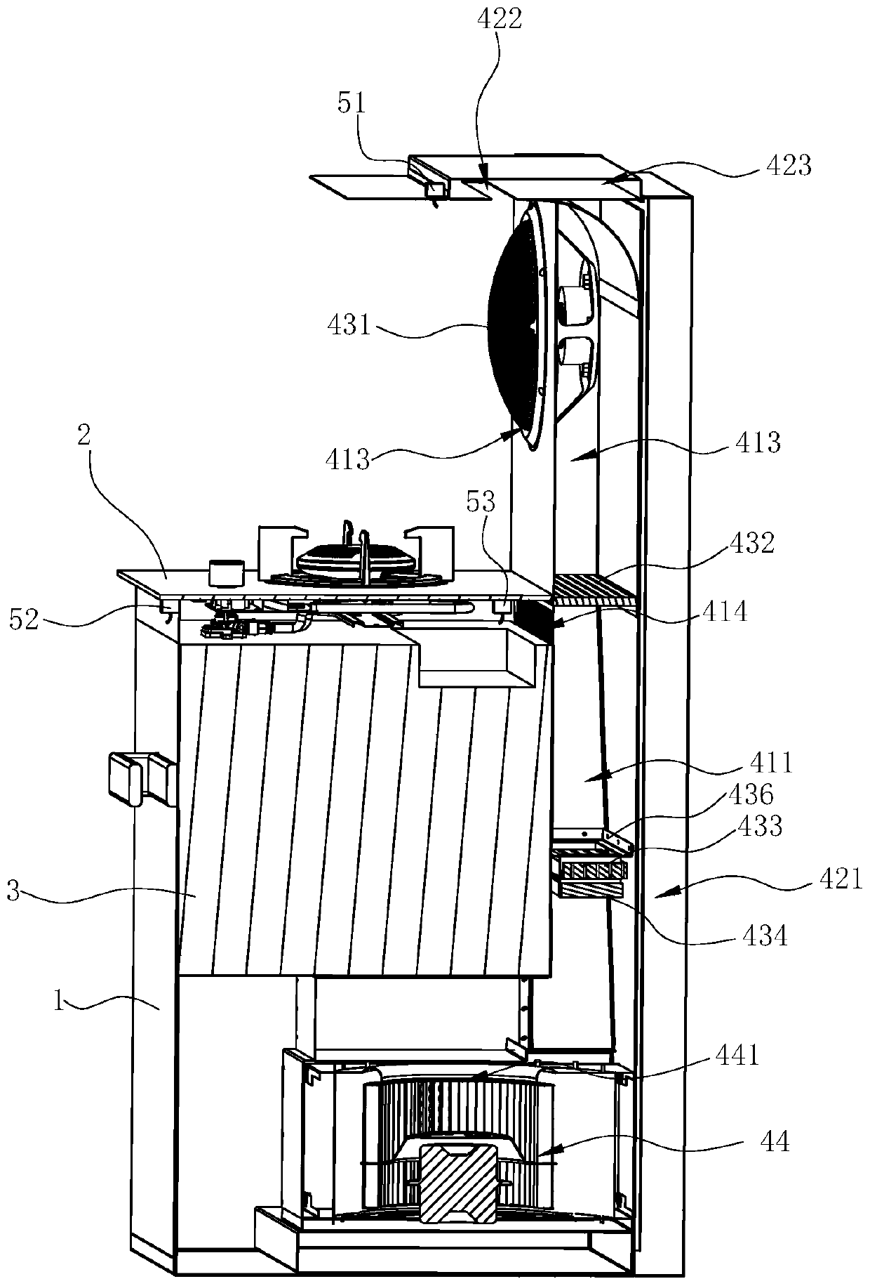
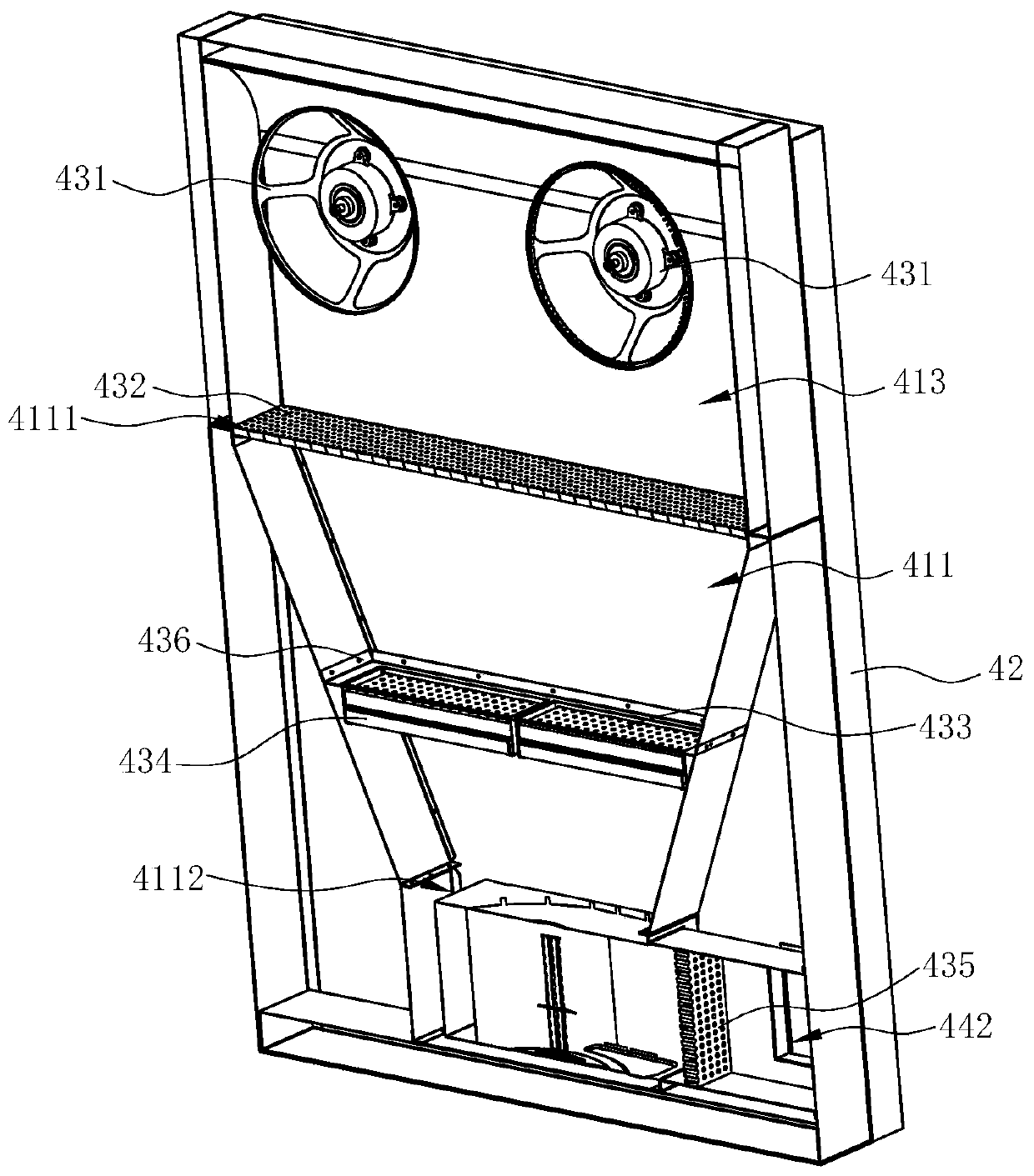
The invention discloses an integrated cooking utensil. The integrated cooking utensil includes a stove body, a stove arranged at the top of the stove body, and a range hood. The range hood includes anair inlet assembly, an air outlet assembly, a filter assembly and a draught fan system. The draught fan system respectively communicates with the air inlet assembly and the air outlet assembly. The air inlet assembly includes an air inlet channel and an air inlet formed in the air inlet channel. The integrated cooking utensil is characterized in that the filter assembly is arranged in the air inlet channel, and in an oil fume flowing path, the filter assembly includes a first stage oil fume filter module for filtering first particles, a second stage oil fume filter module for filtering secondparticles and a third stage oil fume filter module for filtering third particles, wherein the first stage oil fume filter module, the second stage oil fume filter module and the third stage oil fumefilter module are arranged in sequence from upstream to downstream, and the particle sizes of the first particles, the second particles and the third particles decrease gradually. The invention further discloses a control method of the integrated cooking utensil.

Description

technical field [0001] The invention relates to kitchen appliances, in particular to an integrated cooking appliance and a control method thereof. Background technique [0002] With the pursuit of healthy quality of life, in order to achieve high space utilization and beautiful appearance, it is in line with the design trend of open kitchen and kitchen cabinet integration. Embedded and integrated cooking appliances are used more and more, but during the integration process, due to the limited space, the smoke absorption effect and various performances of the range hood will decrease compared with a single product, and the connection of the lower outlet must be Resetting will destroy the existing public flue facilities, which will bring a series of impacts. At the same time, in the existing integrated cooking appliances, the range hood seldom considers the fume purification function, and the cleaning and maintenance of the whole product is inconvenient. [0003] Existing in...

Claims


Application Information

Patent Timeline
Patent Type & Authority Applications(China)
IPC IPC(8): F24C15/20
CPCF24C15/2021F24C15/2035
Inventor 李斌蔡玉标黄友根
Owner NINGBO FOTILE KITCHEN WARE CO LTD
Why Eureka
Try Eureka