Rope remote catching device
A rope, remote technology, applied in the field of anti-riot equipment, can solve the problem of lack of effective equipment, and achieve the effect of reducing the possibility of injury
- Summary
- Abstract
- Description
- Claims
- Application Information
AI Technical Summary
Problems solved by technology
Method used
Image

Examples
Embodiment 1
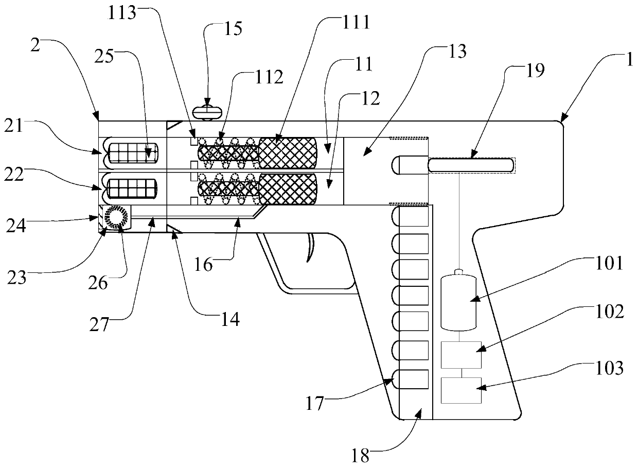
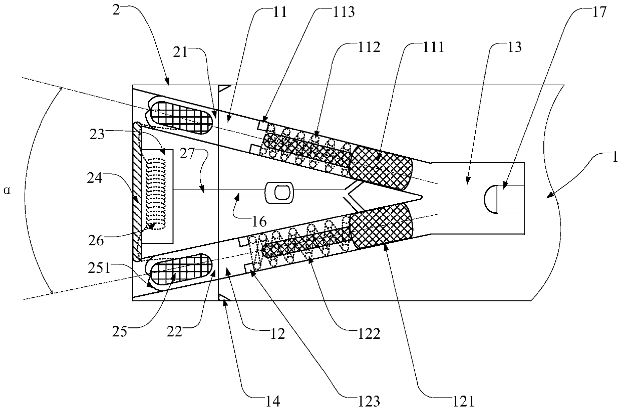
[0064] In Embodiment 1, the rope remote capture device includes: a launching device 1 and a capture rope box 2, and the launch device 1 and the capture rope box 2 are detachably connected through a buckle 14;
[0065] Launching device 1 comprises the first launch tube 11 and the second launch tube 12 arranged therein, and the first launch tube 11 is identical with the second launch tube 12, and is all arranged horizontally, and the first launch tube 11 is arranged on the second launch tube 12, the front end of the first launch tube 11 is fixedly provided with a circular first stop ring 113, behind which the first stop ring 113 is provided with a first variable-diameter launch piston 111, and the first variable-diameter launch piston 111 The front end of the first return spring 112 is a small-diameter cylinder, and its rear end is a large-diameter cylinder. The small-diameter cylinder is fitted with a first return spring 112, and the front end of the first return spring 112 is f...
Embodiment 2
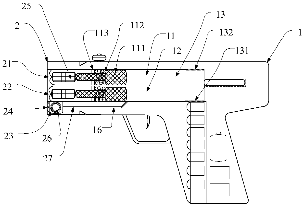
[0074] In Embodiment 2, the end of the first launch tube 11 of the launching device 1 and the end of the second launch tube 12 are arranged in the same horizontal plane, and the two ends are communicated with the body chamber 13 simultaneously, and the front end of the first launch tube 11 is connected to the same horizontal plane. The front ends of the second launch tube 12 are arranged in different horizontal planes, and the front end outlet position of the first launch tube 11 is higher than the front end exit position of the second launch tube 12; the body chamber 13 is used for the explosion of the body 17 to form a high pressure therein airflow;
[0075] The bottom of the launch tube is provided with a vent hole 16, and the vent hole 16 is horizontally arranged to be consistent with the extension direction of the launch tube. In communication with it, the front end of the air leakage through hole 16 is adjacent to the opening ends of the first launch tube 11 and the seco...
Embodiment 3
[0080] In Embodiment 3, the firing assembly 19 includes an electronic lighter 191, a voltage amplification module 192 electrically connected to the electronic lighter 141, and an electronic trigger 193 electrically connected to the voltage amplification module 192, which is adapted to the electronic trigger 193 The firing spring 194. The firing assembly 19 can be arranged at a suitable position in the launching device, for example figure 1 The middle firing assembly 19 is disposed in a cavity on the firing device, as shown by the dashed lines around the firing assembly 19 .
[0081] By pulling the trigger, pressing the firing spring 194 and then pressing the push switch of the electronic lighter 191, a voltage can be generated. Amplify, thereby increasing the voltage and arc length of the output arc of the firing assembly 19, and can detonate the nail-shooting projectile in the projectile chamber.
[0082] The rope remote arresting device disclosed in the embodiment of the p...
PUM
 Abstract
Description
Claims
Application Information
 - R&D
- Intellectual Property
- Life Sciences
- Materials
- Tech Scout
- Unparalleled Data Quality
- Higher Quality Content
- 60% Fewer Hallucinations
Browse by: Latest US Patents, China's latest patents, Technical Efficacy Thesaurus, Application Domain, Technology Topic, Popular Technical Reports.
© 2025 PatSnap. All rights reserved.Legal|Privacy policy|Modern Slavery Act Transparency Statement|Sitemap|About US| Contact US: help@patsnap.com