System for measuring and adjusting antenna radiation pattern

An antenna radiation and measurement technology, applied in the system field, to solve the time-consuming and labor-intensive effect

Inactive Publication Date: 2020-05-22
WANDER PLASTIC
View PDF13 Cites 1 Cited by
  • Summary
  • Abstract
  • Description
  • Claims
  • Application Information

AI Technical Summary

Problems solved by technology

[0004] The embodiment of the present invention discloses a system for measuring and adjusting the antenna radiation pattern, which can solve the problem that traditional measurement and adjustment are independent of each other

Method used


Image

  • System for measuring and adjusting antenna radiation pattern
  • System for measuring and adjusting antenna radiation pattern
  • System for measuring and adjusting antenna radiation pattern

Examples


Embodiment Construction

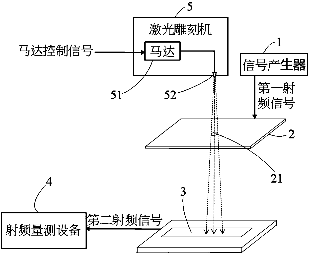
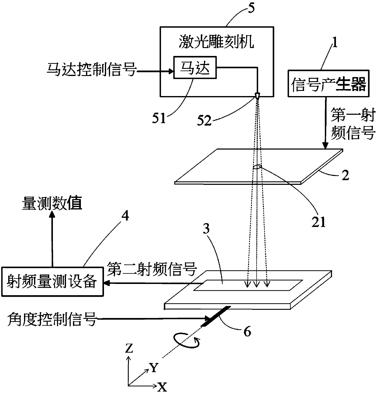
[0017] refer to figure 1 and figure 2 A first preferred embodiment of a system for measuring and adjusting antenna radiation pattern of the present invention includes a signal generator 1 , a standard antenna 2 , an antenna to be tested 3 , a radio frequency measurement device 4 and a laser engraving machine 5 .

[0018] The signal generator 1 is used for providing a first radio frequency signal. The standard antenna 2 is electrically connected to the signal generator 1 to receive the first radio frequency signal and convert the first radio frequency signal into electromagnetic waves, and the standard antenna 2 has a through hole 21 .

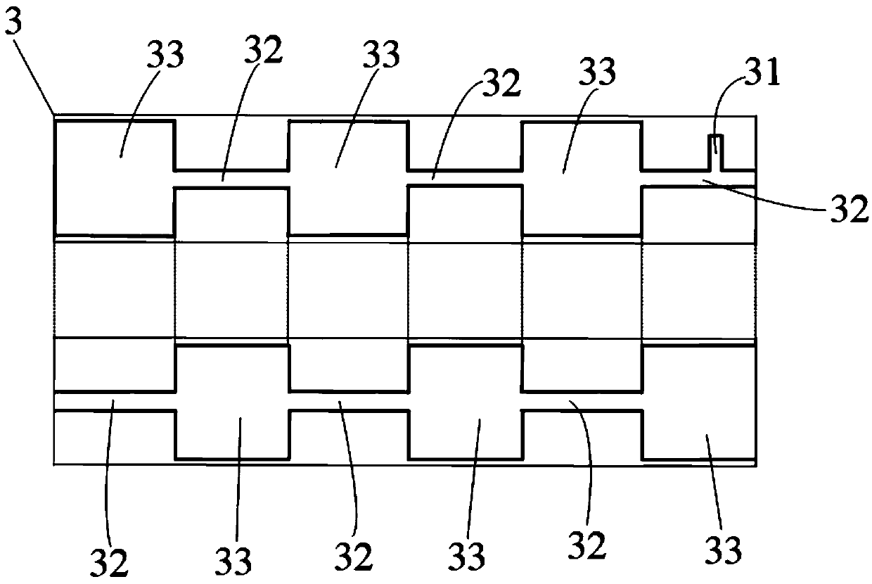
[0019] The antenna 3 to be tested is paired with the standard antenna 2 to receive electromagnetic waves, and convert the electromagnetic waves into a second radio frequency signal for output, and the antenna 3 to be tested includes an adjustment band 31 (see figure 2 ), the adjustment band 31 is a conductor, and the position of the current...


PUM


Abstract

The invention relates to a system for measuring and adjusting an antenna radiation pattern. The system comprises a signal generator, a standard antenna, an antenna to be measured, radio frequency measurement equipment and a laser engraving machine. The signal generator is used for providing a first radio frequency signal. The standard antenna is electrically connected with the signal generator toreceive a first radio frequency signal and convert the first radio frequency signal into electromagnetic waves, and the standard antenna is provided with a through hole. The antenna to be measured receives the electromagnetic waves and converts the electromagnetic waves into a second radio frequency signal and outputs the second radio frequency signal to the radio frequency measurement equipment.The laser outputted by the laser engraving machine passes through the through hole of the standard antenna to engrave the adjusting band of the antenna to be measured so as to adjust the current zeropoint distribution on the antenna to be measured. Therefore, the defect that research and development are inefficient due to the fact that measurement and antenna adjustment are independent in the prior art is overcome.

Description

technical field [0001] The present invention relates to a system, in particular to a system for measuring and adjusting the antenna radiation pattern. Background technique [0002] The traditional antenna measurement system only has the function of measuring antenna radiation parameters. When developing an antenna, engineers must adjust the shape and size of the antenna according to their own experience or the performance evaluation of simulation software. Measure the darkroom and connect the measuring instrument to measure the radiation characteristics. After the measurement, remove the antenna from the measuring instrument and leave the measuring darkroom. Then the engineer manually adjusts the antenna size according to the measurement results. After the adjustment is completed The above-mentioned measurement process is carried out again, so that the cycle is time-consuming and labor-intensive. [0003] The disadvantage of this traditional technique is that the measuremen...

Claims


Application Information

Patent Timeline
Patent Type & Authority Applications(China)
IPC IPC(8): G01R29/10H01Q3/00H01Q1/36
CPCG01R29/10H01Q1/36H01Q3/00
Inventor 万胜枝吕宏晖
Owner WANDER PLASTIC
Why Eureka
Try Eureka