Design and debugging method of a special-shaped reference ring

A debugging method and reference ring technology, applied in the field of reference rings, can solve the problems of difficult adjustment of tuning circuits, cumbersome and complicated debugging steps, etc., and achieve the effect of simplifying the calibration steps and simplifying the debugging steps

Active Publication Date: 2021-09-03
BEIJING JIAODA SIGNAL TECH
View PDF3 Cites 0 Cited by
  • Summary
  • Abstract
  • Description
  • Claims
  • Application Information

AI Technical Summary

Problems solved by technology

[0003] In addition, it is difficult to adjust the tuning circuit of the existing reference ring, and the debugging steps are cumbersome and complicated

Method used


Image

  • Design and debugging method of a special-shaped reference ring
  • Design and debugging method of a special-shaped reference ring
  • Design and debugging method of a special-shaped reference ring

Examples


Embodiment 1

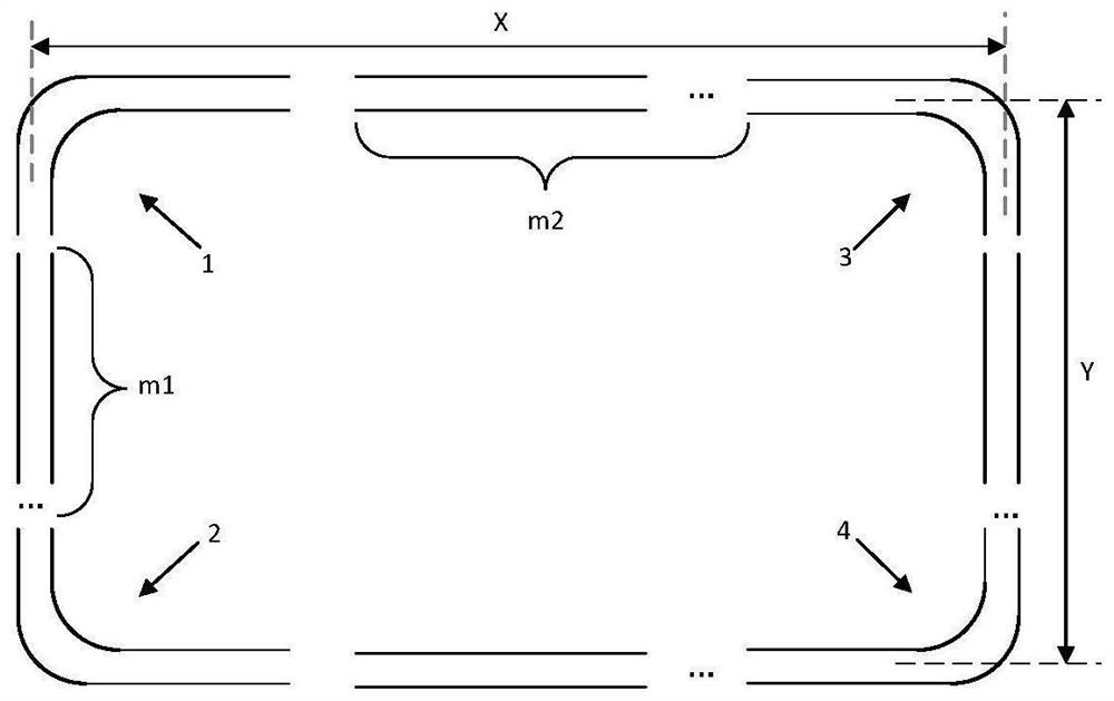
[0037] A four-sided reference ring structure Figure 2A Indicated. The X and Y represent the size of the reference ring length and wide, which consists of several joints, including 4 knots, symmetrical straight copper strips (ie Figure 2A In the arrow refers to it), and several linear copper strips (ie Figure 2A Mix M1 and M2). Among them, the reference ring wide side (ie Figure 2A The number of copper strips of the line Y is M1, long side (ie Figure 2A The number of linear copper strips is M2 in the middle x shown. The present invention defines the number M1 M1 of the linear copper strip, M2 is as follows:

[0038]

[0039] The 4-section is completely symmetrical. Figure 2B As shown, since the structure is completely symmetrical, the size is consistent, and the present invention is plotted only one of them. The long and wide dimensions of the right-angled copper strips are represented by A and B.

[0040] Some line copper strips such as Figure 2C As shown, since it is a structur...

Embodiment 2

[0048] A triangular reference ring structure Figure 6A Indicated. The present invention considers an equilateral triangular structure, X represents a triangular side length size, which is composed of a solid copper ring, including 3 sections, completely symmetrical rounded copper strips (ie Figure 6A In the arrow refers to it), and several linear copper strips (ie Figure 6A The m1 is shown). Among them, the number of copper strips of the reference loop line is M1, defined as follows:

[0049]

[0050] The 3-section is completely symmetric rounded copper strip such as Figure 6B As shown, since it is a 3-section complete symmetrical structure, the size is consistent, this diagram only draws one of them. Rounded copper strip edge length with A represents.

[0051] Some linear copper strips (such as Figure 6C As shown), since the size is fully consistent, this figure exists only one of the following. Linear copper strips length with B represent.

[0052] The value of the M1 of the p...

Embodiment 3

[0057] The different type reference ring of the present embodiment, the same copper ring as the same structure, respectively, in 27 MHz and 4 MHz. Cut copper strips in each copper ring are connected by printed circuit boards (eg Figure 4 The PCB board is shown). The resonant circuit of each board is LC resonant circuit (eg Figure 5b Disted), equivalent resonance formula is

[0058] Among them inductance L (eg Figure 5b The inductance L shown) is the inductive value of the single-segment copper ring, and the inductance value of the entire copper ring before the cutting segment is measured, and the single-segment electrical value is calculated according to the number of cutting segments, and the like is erected inductance L.

[0059] Among them, the capacitance value c (eg Figure 5b The medium capacitance C is shown in accordance with the desired resonance point to debug different inductance values. Adjusting at 27M ring and 4M ring, respectively.

[0060] The reference ring tuning...


PUM


Abstract

The invention provides a method for designing and debugging a special-shaped reference ring. The method includes the following steps: in the first step, the size of the reference ring is determined according to the measured special-shaped transponder, and the size of the reference ring is determined to be consistent with the size of the transponder. This makes two copper rings with dual output, and measures the inductance value C of the entire copper ring A ; In the second step, in order to ensure the uniform distribution of the magnetic field, the copper ring is uniformly cut, that is, the length of each copper strip is basically the same, and the length of a single copper strip cannot exceed 300mm, and the cutting is not performed at the corner; the third step is tuning, each The tuning circuit at the frequency point is equivalent to one in which only the capacitance C can be adjusted, and the capacitance value C can be adjusted according to the required resonance frequency; through the above method, special-shaped reference rings for various special-shaped transponders can be produced to meet the needs of special-shaped transponders. Calibration requirements; and the tuning steps of the reference loop simplifies the tuning circuit and debugging steps of the existing reference loop.

Description

Technical field [0001] The present invention relates to the field of railway communication signals, and more particularly to a reference ring of an expanded reference area. Background technique [0002] The reference ring is a cyclic conductor around the effective reference region, is a calibration tool consistent with the transponder reference area. Mainly the uplink and RF field consistency of the calibration transponder, input and output characteristics, and uplink features. In response to the current rail application, it can be divided into standard dimensional transponders and large-size transponders according to standard TB / T 3544, and have their respective reference loops production standards. However, when the CBTC mode is currently realized, the wake-up zero setting of the unmanned sleep wake-up function is called an extended transponder, and there is no applicable extended reference ring. In order to perform the extensive transponder, this shaped transponder related t...

Claims


Application Information

Patent Timeline
Patent Type & Authority Patents(China)
IPC IPC(8): H04B17/11H04B17/21H04B1/59
CPCH04B1/59H04B17/11H04B17/21
Inventor 王若瑾刘浩袁新娜王秉森
Owner BEIJING JIAODA SIGNAL TECH
Why Eureka
Try Eureka