Method for implementing self-calibration of current-limiting current value of motor controller

A motor controller and self-calibration technology, used in electrical testing/monitoring, etc., can solve the problems of difficulty in calibration and correction of current limiting current value, reduced production efficiency, complicated operation, etc., so as to simplify the current limiting current debugging steps and improve production efficiency. , the effect of a wide range of applications

Inactive Publication Date: 2014-02-05
SICHUAN JINWANGTONG ELECTRONICS SCI & TECH
View PDF8 Cites 0 Cited by
  • Summary
  • Abstract
  • Description
  • Claims
  • Application Information

AI Technical Summary

Problems solved by technology

[0003] One of the purposes of the present invention is to solve the above-mentioned shortcomings, and provide a method for realizing the self-calibration of the current limiting current value of the motor controller, in order to solve the difficulty in calibrating and correcting the current limiting current value in the detection of the motor controller product in the prior art, and the operation is complicated And the error is large, which reduces the production efficiency of the product and other technical problems

Method used


Image

  • Method for implementing self-calibration of current-limiting current value of motor controller
  • Method for implementing self-calibration of current-limiting current value of motor controller

Examples


Embodiment Construction

[0018] The present invention will be further elaborated below in conjunction with the accompanying drawings.

[0019] The first embodiment of the present invention provides a method for realizing the self-calibration of the current limiting current value of the motor controller, and the method is carried out according to the following steps:

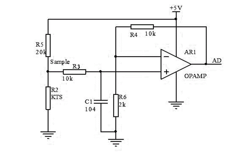
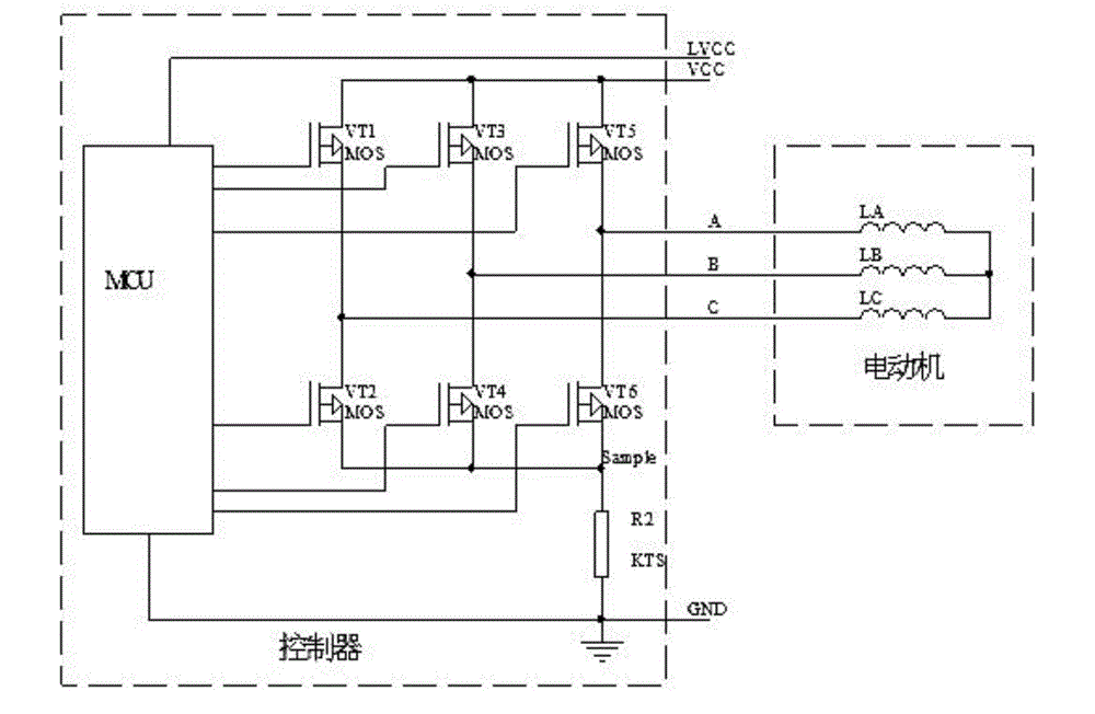
[0020] Step A. Collect self-calibration data, connect the motor controller directly to the constant current power supply, and make the constant current power supply output a constant current equal to the target current limiting current value. The voltage value at the terminal is cyclically sampled, and the average value of the multiple voltage values ​​collected cyclically is calculated by the average value calculation method, and the average value is stored in the storage unit in the motor controller as self-calibration data;

[0021] Step B, when the motor controller is connected to the motor and is in the running state, the single-chi...


PUM


Abstract

The invention discloses a method for implementing self-calibration of a current-limiting current value of a motor controller, and belongs to a detection method for the motor controller. The method comprises the following steps that: self-calibration data is acquired, wherein the motor controller is directly connected to a constant current power supply, the constant current power supply outputs constant current equal to a target current-limiting current value, and in the process that the constant current passes through a sampling resistor, a singlechip circularly samples voltage values at the two ends of the sampling resistor; and if the real-time voltage values at the two ends of the sampling resistor exceed a reference voltage value or a voltage value corresponding to an initial current-limiting current value, the pulse-width modulation (PWM) duty ratio output by the sampling resistor is reduced, and the on-time of a metal-oxide-semiconductor field effect transistor (MOSFET) in the motor controller is shortened, so that the current is reduced, and the working current of the motor controller is always kept to be less than or equal to the current-limiting current value. The method comprises simple steps, is suitable for self-calibration debugging of the current-limiting current of motor controllers of electric vehicles of all types and has a wide application range.

Description

technical field [0001] The invention relates to a detection method of a motor controller, and more specifically, the invention mainly relates to a method for realizing self-calibration of a current limiting current value of a motor controller. Background technique [0002] The electric vehicle controller is used for the maximum current control of the electric vehicle motor and the motor speed and underspeed protection. In order to ensure the consistency of product application, the maximum current will be tested and calibrated when it is produced. At present, the motor controller A common method for calibrating the maximum current is as figure 1 As shown, when the sampling current flows through the sampling resistor R2, a voltage proportional to the current is generated at Sample, and the voltage is amplified by the operational amplifier and then output to the AD port of the microcontroller. Sampling resistor R2, because the current flowing through the sampling resistor is g...

Claims


Application Information

Patent Timeline
Patent Type & Authority Patents(China)
IPC IPC(8): G05B23/02
Inventor 谌光武
Owner SICHUAN JINWANGTONG ELECTRONICS SCI & TECH
Why Eureka
Try Eureka