
Unmanned aerial vehicle take-off and landing platform adjusted based on connecting rod linkage principle

A technology for take-off and landing platforms and unmanned aerial vehicles, which is applied in the field of aerospace, can solve the problems of non-adjustable take-off and landing platform area, increased preparation time, and inability to apply unmanned aerial vehicles, etc., so as to improve practicability and applicability, increase Stability, the effect of improving stability

Inactive Publication Date: 2020-05-26
陈志华
View PDF0 Cites 0 Cited by
  • Summary
  • Abstract
  • Description
  • Claims
  • Application Information

AI Technical Summary

Problems solved by technology

[0002] With the advent of the information age and the rapid development of Internet technology, drones are widely used in various fields due to their advantages of convenient operation and wide applicability. In order to ensure the stability of use, it is generally necessary to Special take-off and landing platform, but the area of ​​the existing take-off and landing platform is fixed and non-adjustable, and cannot be applied to drones of different sizes, so users generally configure different take-off and landing platforms for different drones, increasing At the same time, the existing adjustable platforms on the market generally have the problem of difficult adjustment, which increases the time for preparation work in the process of use, and seriously even affects the progress of the entire work. limitation

Method used


Image

  • Unmanned aerial vehicle take-off and landing platform adjusted based on connecting rod linkage principle
  • Unmanned aerial vehicle take-off and landing platform adjusted based on connecting rod linkage principle
  • Unmanned aerial vehicle take-off and landing platform adjusted based on connecting rod linkage principle

Examples


Embodiment Construction

[0027] The following will clearly and completely describe the technical solutions in the embodiments of the present invention with reference to the accompanying drawings in the embodiments of the present invention. Obviously, the described embodiments are only some, not all, embodiments of the present invention. Based on the embodiments of the present invention, all other embodiments obtained by persons of ordinary skill in the art without making creative efforts belong to the protection scope of the present invention.

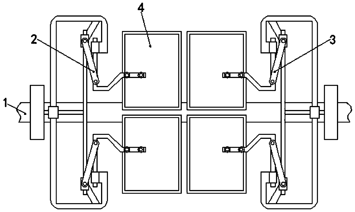
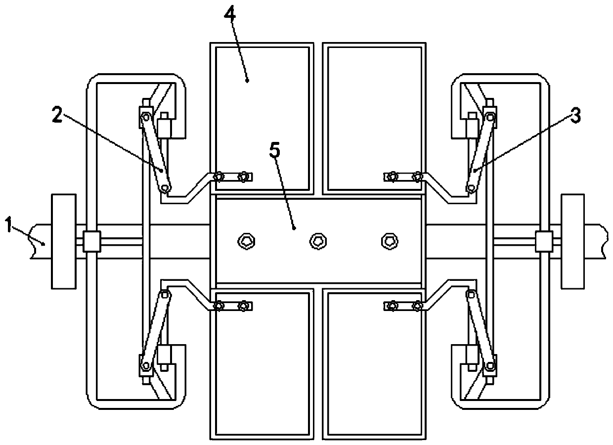
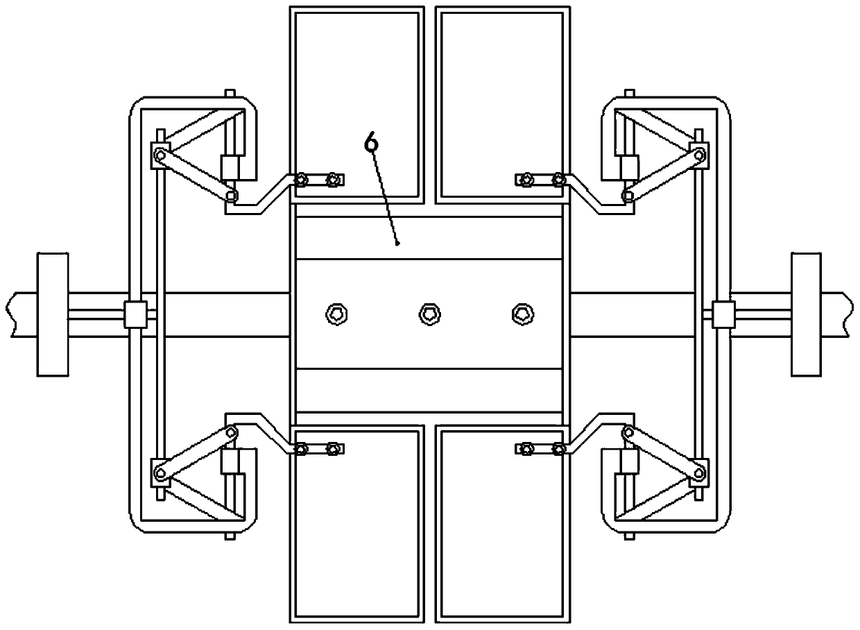
[0028] see Figure 1-7 :

[0029] The unmanned aerial vehicle take-off and landing platform adjusted based on the linkage principle of connecting rods includes a base plate 1, a left adjustment mechanism 2, a right adjustment mechanism 3, a movable plate 4, a main fixed plate 5, an auxiliary fixed plate 6, a chute 7, and a connecting plate. Rod 8, hinge ring 9 and tie rod 10.

[0030] Wherein: the left adjusting mechanism 2 comprises a sliding seat 21, a mov...


PUM


Abstract

The invention discloses an unmanned aerial vehicle take-off and landing platform adjusted based on a connecting rod linkage principle and belongs to the technical field of aerospace. The platform comprises a bottom plate; the left side and right side of the front face of the bottom plate are movably connected with a left adjusting mechanism and a right adjusting mechanism correspondingly; two movable plates are movably connected to the opposite sides of the left adjusting mechanism and the right adjusting mechanism; a main fixing plate is movably connected to the bottoms of the movable plates;an auxiliary fixing plate is movably connected to the outer side of the main fixing plate; a sliding groove is formed in the back face of the bottom plate; two connecting rods are movably connected to the outer side of the sliding groove. According to the unmanned aerial vehicle take-off and landing platform is adjusted based on the connecting rod linkage principle, the bottom plate can provide supporting for a structure connected with the bottom plate and maintain the position stability of the structure, and therefore, stable connection between all structures in a working process is guaranteed, the overall stability of the device is improved; the left adjusting mechanism and the right adjusting mechanism can provide supporting for the two movable plates respectively, and therefore, the stability of the device is improved.

Description

technical field [0001] The invention relates to the field of aerospace technology, in particular to an unmanned aerial vehicle take-off and landing platform adjusted based on the linkage principle of connecting rods. Background technique [0002] With the advent of the information age and the rapid development of Internet technology, drones are widely used in various fields due to their advantages of convenient operation and wide applicability. Special take-off and landing platform, but the area of ​​the existing take-off and landing platform is fixed and non-adjustable, and cannot be applied to drones of different sizes, so users generally configure different take-off and landing platforms for different drones, increasing At the same time, the existing adjustable platforms on the market generally have the problem of difficult adjustment, which increases the time for preparation work in the process of use, and even affects the progress of the entire work seriously. limitati...

Claims


Application Information

Patent Timeline
Patent Type & Authority Applications(China)
IPC IPC(8): B64F1/00F16H21/44
CPCB64F1/00F16H21/44
Inventor 陈志华
Owner 陈志华
Learn More