Automatic sealing system for IC product packaging

A technology of automatic sealing and product packaging, applied in the direction of automatic packaging control, packaging, packaging machines, etc., can solve the problems of decreased operation efficiency, injury to the operator's hand, hand fatigue, etc., to save equipment costs, improve propulsion efficiency, Good effect of limit coordination

Pending Publication Date: 2020-05-26
四川明泰微电子科技股份有限公司
View PDF0 Cites 3 Cited by
  • Summary
  • Abstract
  • Description
  • Claims
  • Application Information

AI Technical Summary

Problems solved by technology

[0003] Since the rubber plug is currently manually operated by manpower, the long-term operation will hurt the hands of the operator and make the hand tired, which will cause a decrease in work efficiency; on the other hand, after the packaging tube is inserted into the rubber plug, the operator needs to press The number of packaging tubes is bundled in points. These two factors will account for 50% of the working time of the punching and forming process.

Method used


Image

  • Automatic sealing system for IC product packaging
  • Automatic sealing system for IC product packaging
  • Automatic sealing system for IC product packaging

Examples


Embodiment 1

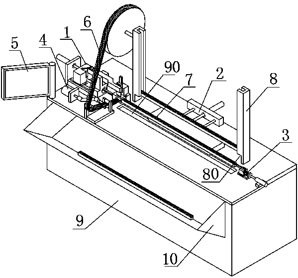
[0038] Such as figure 1 As shown, this embodiment provides an automatic sealing system for IC product packaging, including a workbench 9, and a rubber plug plugging assembly 1, a pushing assembly 2, a pushing assembly 3, and a rubber stopper guide assembly provided on the workbench 9. 4. The storage component 8, the workbench 9 is provided with a collection hole 90, the rubber plug plugging component 1 and the pushing component 3 are arranged at both ends of the collection hole 90, and the collection hole 90 and the pushing component 2 are located on both sides of the storage component 8;

[0039] The storage assembly 8 is used for stacking and storage of the packaging tube 7 parallel to the collection hole 90, and the bottom end of the storage assembly 8 is provided with a discharge port 80 adapted to the single packaging tube 7;

[0040] The rubber plug plugging assembly 1 includes a plugging cavity 1011, a cutter 111, and a plug rod 108. The plugging cavity 1011 and the collecti...

Embodiment 2

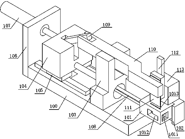
[0046] Such as figure 2 As shown, on the basis of Embodiment 1, this embodiment provides a specific structure of a rubber plug plugging assembly 1. The rubber plug plugging assembly 1 further includes a plugging head 101. One side of the plugging head 101 is fixed to the plugging head base 102, and the opposite side is provided with a rubber plug strip insertion hole 1012. The plugging cavity 1011 is penetrated and opened in the plugging head 101. On the end surface, the top surface of the plugging head 101 is provided with a cutting hole 1013, and the plugging cavity 1011, the rubber plug insertion hole 1012, and the cutting hole 1013 are connected;

[0047] The cutter 111 is installed above the plugging head 101, and the cutter 111 can be vertically inserted into the plugging cavity 1011 through the cutting hole 1013, and punching the rubber stopper 6;

[0048] The plug rod 108 is horizontally spaced and arranged on the side of the plug driving head 101 away from the collection ...

Embodiment 3

[0059] Further, on the basis of the above embodiment 2, such as figure 2 As shown, in this embodiment, the cutter 111 and the push rod 108 share a driving mechanism, which facilitates continuous control of the two actions of cutting and plugging, and can save equipment cost and energy consumption. The cutter 111 is vertically installed at the front end of a second rotating arm 110, the end of the second rotating arm 110 is hingedly connected to the front end of a first rotating arm 109, and the end of the first rotating arm 109 is connected with a plugging cylinder 107; The tail end of the rod 108 is horizontally connected to the plugging cylinder 107. When working, first, the plugging cylinder 107 drives the cutter 111 downwards and vertically into the plugging cavity 1011 through the hinged first rotating arm 109 and the second rotating arm 110, and punching and cutting off the rubber stopper strip 6. The plugging cylinder 107 will also push the plug rod 108 to move a certai...


PUM


Abstract

The invention provides an automatic sealing system for IC product packaging. The automatic sealing system comprises a worktable with a collection hole; a rubber plug inserting and plugging assembly and an ejecting and pushing assembly are arranged on two ends of the collection hole; the collection hole and a propulsion assembly are located on both sides of a storage assembly; the storage assemblyis used for storing packaging tubes parallel to the collection hole in a stacked manner; a discharge opening adaptive to the single packaging tubes is formed in the bottom end of the storage assembly;the rubber plug inserting and plugging assembly comprises an inserting and plugging cavity, a cutter and a pushing and plugging rod; the inserting and plugging cavity and the collection hole are collinear; after the propulsion assembly pushes the packaging tubes on the lowest layer to a part above the collecting hole through the discharge opening, the ejecting and pushing assembly acts on the rear ends of the packaging tubes, so that opening ends of the packaging tubes are inserted into the inserting and plugging cavity; and after a rubber plug strip guiding assembly transfers a rubber plug strip to the inserting and plugging cavity, the cutter can cut off the rubber plug strip into single rubber plugs, and the pushing and plugging rod can drive the rubber plugs to be inserted into the opening ends of the packaging tubes. Through the cooperation of the cutter and the pushing and plugging rod in the inserting and plugging cavity, the rubber plug strip is automatically cut off and the packaging tubes are blocked at the same time, and the packaging tubes are automatically sealed and collected efficiently and quickly.

Description

Technical field [0001] The invention relates to the technical field of IC product packaging equipment, in particular to an automatic sealing system for IC product packaging. Background technique [0002] In the cutting and forming process in the field of integrated circuit packaging, there is a package model of DIP plastic packaging products. After the product is stamped and formed, the equipment will push it into the packaging tube ( Figure 7 As shown), the number of products in the packaging tube is a fixed value. Leave a space above the length of the product at the entrance of the packaging tube. Manually insert the rubber stopper into the empty part of the packaging tube. The rubber stopper is made of soft plastic, which is larger than the opening of the packaging tube. The size is 0.5~1mm, the rubber stopper will not fall out after being inserted, and the product will not be poured out. [0003] Since the rubber stopper is currently manually operated by manpower, long-term wo...

Claims


Application Information

Patent Timeline
IPC IPC(8): B65B7/28B65B57/00B65B65/08
CPCB65B7/2821B65B57/00B65B65/08
Inventor 胡冬
Owner 四川明泰微电子科技股份有限公司
Why Eureka
Try Eureka