Cutting fluid recovery device for machining

A technology of mechanical processing and recycling device, applied in the field of mechanical processing, can solve the problems of clogging of mesh holes, affecting the effectiveness of long-term recycling operations, etc., and achieve the effect of improving adsorption effect and enhancing the effect of treatment and reuse.

Inactive Publication Date: 2020-05-26
任路明
View PDF0 Cites 1 Cited by
  • Summary
  • Abstract
  • Description
  • Claims
  • Application Information

AI Technical Summary

Problems solved by technology

[0003] Cutting fluid is an industrial liquid used in metal cutting and grinding to cool and lubricate cutting tools and workpieces. Cooling performance, lubricating performance, anti-rust performance, degreasing and cleaning function, anti-corrosion function, and easy dilution characteristics. When cutting fluid is used in the actual machining process, a large amount of metal debris will be brought out, and the cutting fluid with solid debris is directly removed It will cause waste of resources, and the cutting fluid is often recovered by filtering through a filter. However, in the process of recycling the cutting fluid, the cutting fluid is directly passed into the flat filter plate, and the filtered solid impurities are easy to level. Laying on the screen plate will cause mesh blockage, which will affect the effectiveness of long-term recovery operations

Method used


Image

  • Cutting fluid recovery device for machining
  • Cutting fluid recovery device for machining
  • Cutting fluid recovery device for machining

Examples


Embodiment 1

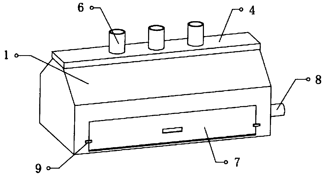
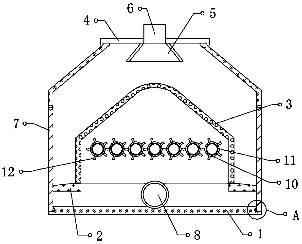
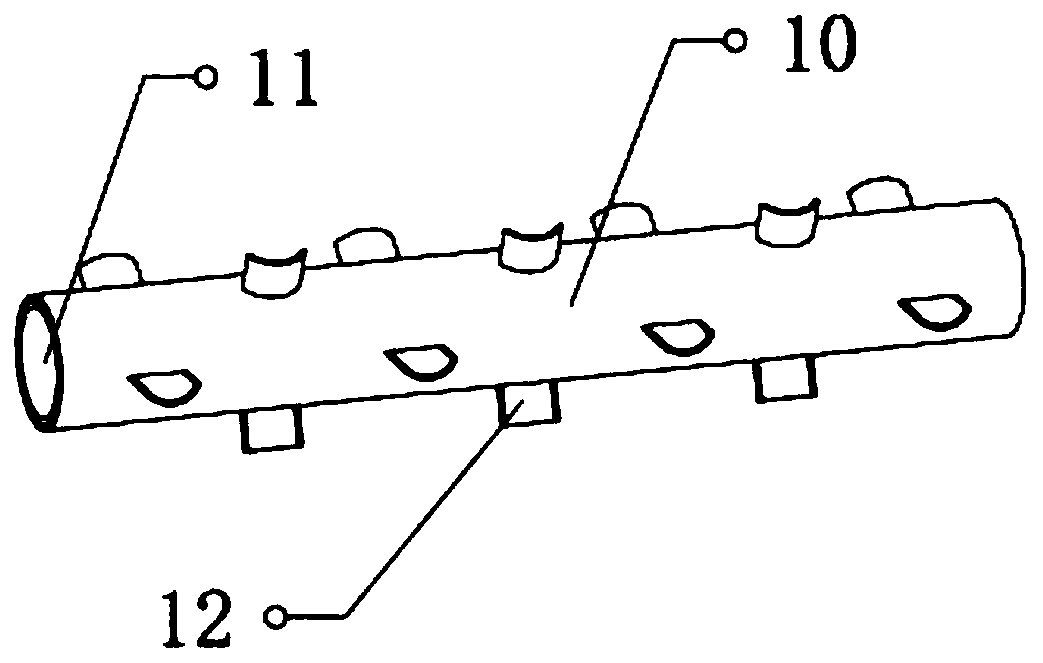
[0028] refer to Figure 1-4 , a cutting fluid recovery device for mechanical processing, including a box body 1, fixing pieces 2 are fixed at the bottom of both ends between the inner walls on both sides of the box body 1, and a filter screen is fixed between the top outer walls of the two fixing pieces 2 Plate 3, the filter screen plate 3 is set as a box-like structure with an open bottom, and the middle position of the top outer wall of the filter screen plate 3 is set as an upwardly protruding arc structure, and both ends of the top outer wall of the filter screen plate 3 are set to be inclined downward The inclined surface, and a storage cavity is formed between the two ends of the filter screen plate 3 and the inner walls of both ends of the box body 1, the top of the box body 1 is open, and the bottom end of the outer wall of the box body 1 is fixed with a liquid outlet pipe 8. The outer walls of both ends of the box body 1 are provided with fixing grooves, and the top o...

Embodiment 2

[0035] refer to Figure 5 , a cutting fluid recovery device for mechanical processing, the top of the inner wall at both ends of the box body 1 is set as an inclined surface, and the inclined surface at the top of the inner wall at both ends of the box body 1 is parallel to the inclined surface at both ends of the top end of the filter screen plate 3, the box body 1 The tops of the inner walls at both ends are provided with installation grooves, and the inner walls of the installation grooves are fixed with electric guide rails 15, and the bottom of the electric guide rails 15 is connected with a connecting plate 16 placed obliquely, and the bottom of the connecting plate 16 is fixed with bristles 17, and the bottom of the bristles 17 In contact with the top of the filter screen plate 3 , an electric telescopic rod 18 is fixedly connected between the bottom of the electric guide rail 15 and the top of the connecting plate 16 .

[0036] During use, during normal filtration and ...


PUM


Abstract

The invention belongs to the technical field of machining, and particularly relates to a cutting fluid recovery device for machining. In order to solve the problem that in the prior art, a flat-plate-shaped filter screen is used for filtering and recycling cutting fluid, and blocking is likely to happen, the following scheme is put forward: the device comprises a box body; fixing pieces are fixedto the bottoms of the two ends between the inner walls of the two sides of the box body; a filter screen plate is fixed between the outer walls of the tops of the two fixing pieces; the filter screenplate is arranged to be of a box-shaped structure with an opening in the bottom, the middle of the outer wall of the top of the filter screen plate is arranged to be of an arc-shaped structure protruding upwards, the two ends of the outer wall of the top of the filter screen plate are both arranged to be inclined faces inclining downwards, and storage cavities are formed between the two ends of the filter screen plate and the inner walls of the two ends of the box body. The filtered solid impurities are scoured downwards along the inclined face, so that the blockage of meshes due to the fact that the solid impurities are flatly laid on the filter screen plate can be avoided, the solid impurities are scoured into the storage cavity to be accumulated, and the long-time effective operation offiltering and recycling operation is ensured.

Description

technical field [0001] The invention relates to the technical field of machining, in particular to a cutting fluid recovery device for machining. Background technique [0002] Machining refers to the process of removing material through mechanical precise machining. Machining refers to the process of changing the shape or performance of a workpiece through a mechanical device. According to the difference in processing methods, it can be divided into cutting processing and pressure processing. Among them, cutting fluid is often used in the cutting process. [0003] Cutting fluid is an industrial liquid used in metal cutting and grinding to cool and lubricate cutting tools and workpieces. Cooling performance, lubricating performance, anti-rust performance, degreasing and cleaning function, anti-corrosion function, and easy dilution characteristics. When cutting fluid is used in the actual machining process, a large amount of metal debris will be brought out, and the cutting f...

Claims


Application Information

Patent Timeline
Patent Type & Authority Applications(China)
IPC IPC(8): C10M175/00B03C1/30
CPCB03C1/30C10M175/00C10M175/0058C10M175/0066
Inventor 任路明
Owner 任路明
Why Eureka
Try Eureka