Environment-friendly flue gas denitration machine
An environmentally friendly, denitrification technology, applied in the direction of dispersed particle separation, chemical instruments and methods, combined devices, etc., can solve the problems affecting the quality of denitrification, containing impurities, etc.
- Summary
- Abstract
- Description
- Claims
- Application Information
AI Technical Summary
Problems solved by technology
Method used
Image

Examples
Embodiment 1
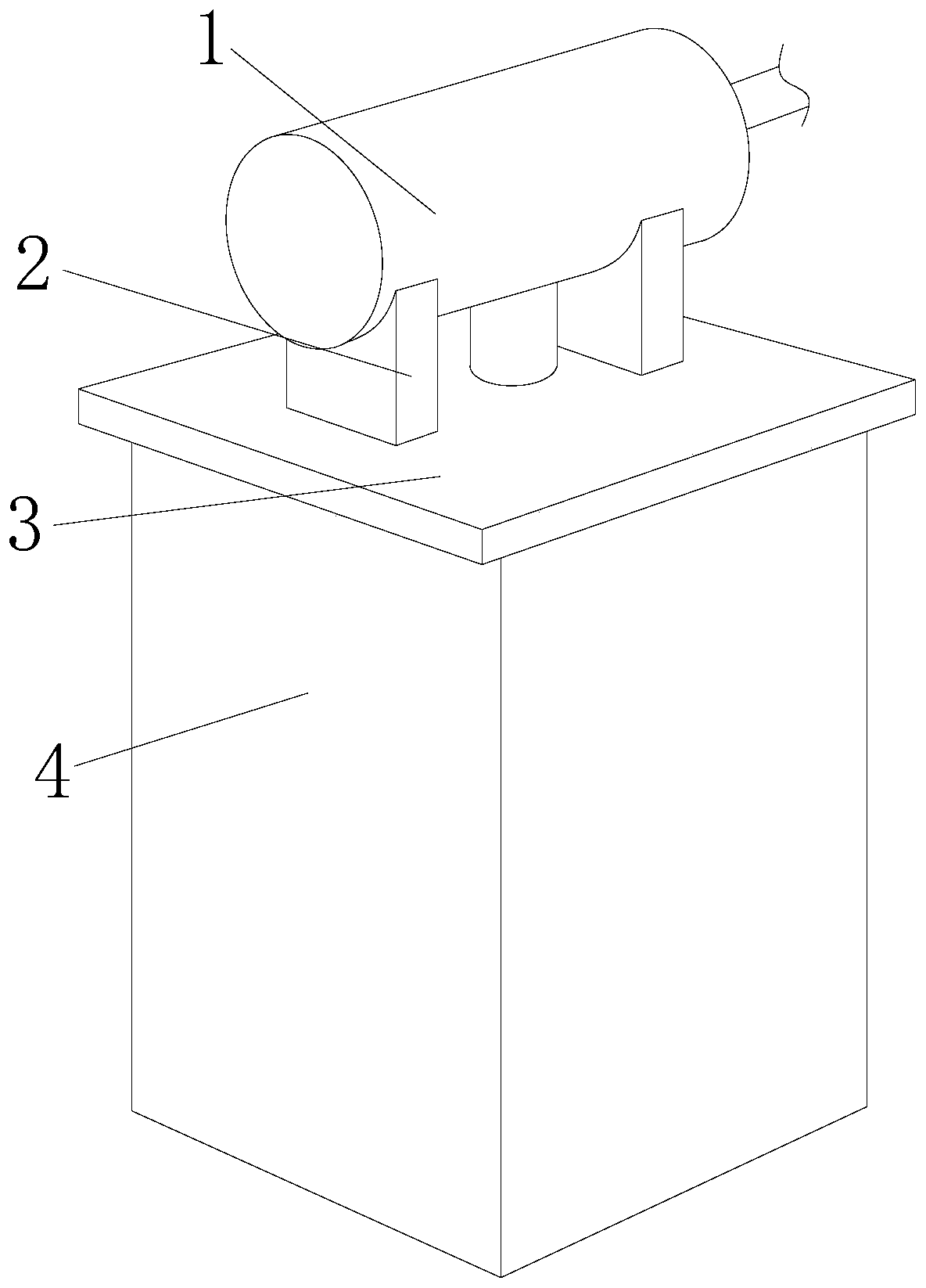
[0029] see Figure 1-Figure 8 , the present invention provides an environment-friendly flue gas denitrification machine, the structure of which includes a particle removal device 1, a support block 2, a fixed plate 3, and a denitrification chamber 4. The bottom of the particle removal device 1 is provided with a support block 2, and the support block 2 is fixedly connected with the particle removal device 1, the support block 2 is provided with two, and is set up in a symmetrical structure, the support block 2 is fixed on the fixed plate 3, and the fixed plate 3 is connected with the denitrification chamber 4, so The center of the top of the denitrification chamber 4 is provided with a connecting pipe, and communicates with the particle removal device 1 through the connecting pipe;
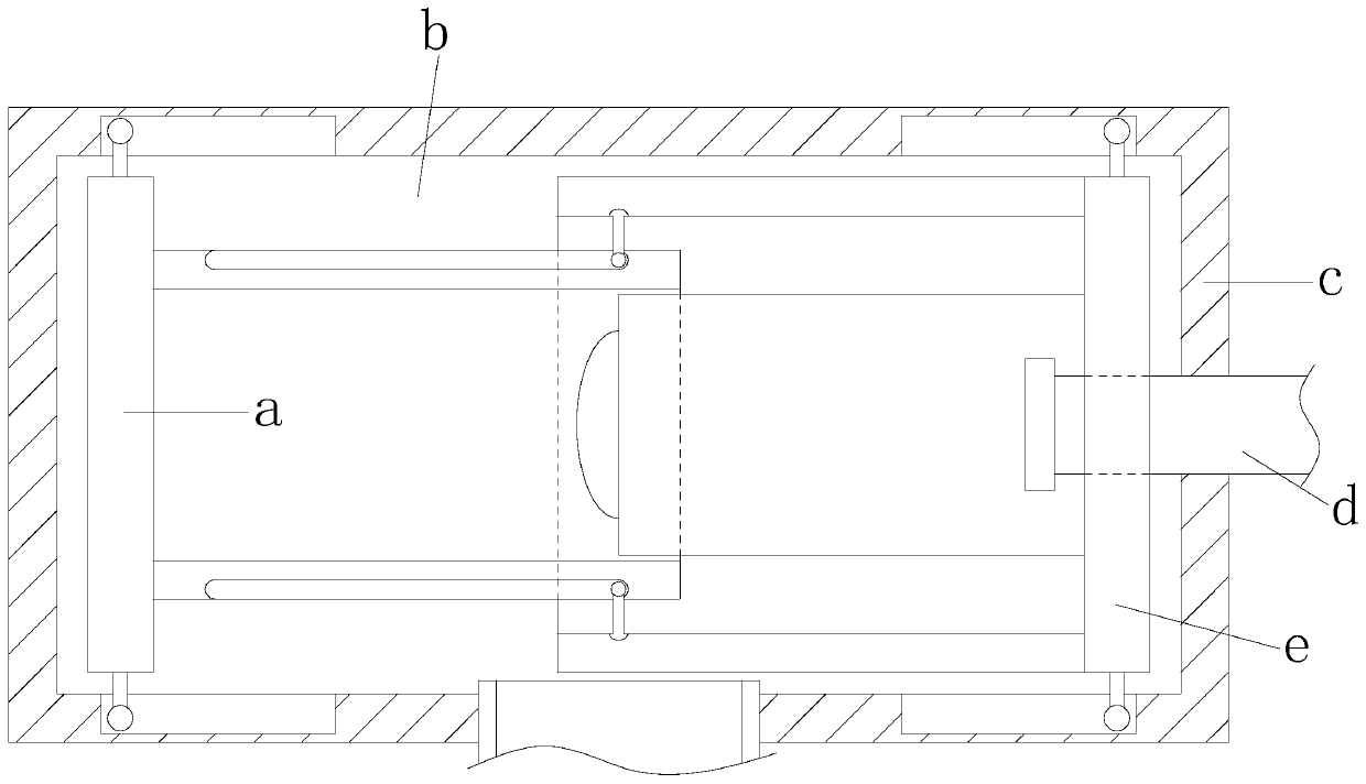
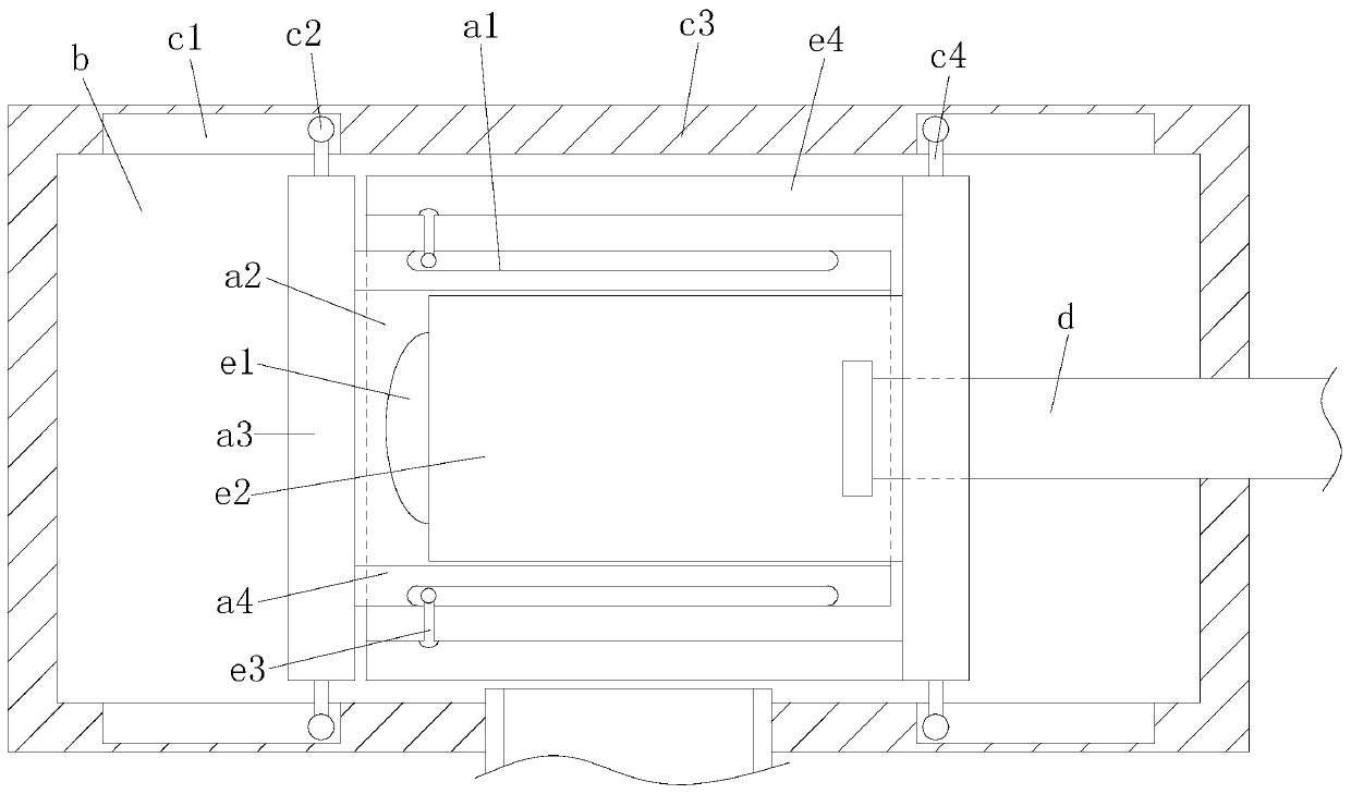
[0030] The particle removal device 1 is composed of a sub-pipe a, a working chamber b, a wall structure c, an external pipe d, and a main pipe e, the sub-pipe a cooperates with the main pipe e, an...
Embodiment 2
[0040] see Figure 1-Figure 3 , the present invention provides an environment-friendly flue gas denitrification machine, the structure of which includes a particle removal device 1, a support block 2, a fixed plate 3, and a denitrification chamber 4. The bottom of the particle removal device 1 is provided with a support block 2, and the support block 2 is fixedly connected with the particle removal device 1, the support block 2 is provided with two, and is set up in a symmetrical structure, the support block 2 is fixed on the fixed plate 3, and the fixed plate 3 is connected with the denitrification chamber 4, so The center of the top of the denitrification chamber 4 is provided with a connecting pipe, and communicates with the particle removal device 1 through the connecting pipe; the particle removal device 1 is composed of a sub-pipe a, a working chamber b, a wall structure c, an external pipe d, and a main pipe e , the sub-pipe a matches the main pipe e, the main pipe e co...
PUM
 Abstract
Description
Claims
Application Information