Auxiliary machine for manufacturing and forming anchor rod for power accessory equipment

A technology for auxiliary machinery and accessories, which is applied in the field of auxiliary machinery for making wire rods for electrical accessories and equipment. It can solve the problems of high production cost, poor continuity, and low degree of automation, and achieve the effect of beautiful and consistent welding length and improved economic practicability.

Active Publication Date: 2020-05-29
马鞍山市华能电力线路器材有限责任公司
View PDF6 Cites 1 Cited by
  • Summary
  • Abstract
  • Description
  • Claims
  • Application Information

AI Technical Summary

Problems solved by technology

[0003] Existing wire rods mainly include a rod body and a pull ring. The pull ring is fixed on the top of the rod body and has an integral structure with the rod body. When making it specifically, a round steel rod is first cut, and then its top is bent into a Closed shape, and then weld the junction of the ring body and the rod body together with a welding torch to complete the production of the wire rod, but the production and bending of the existing wire rod is completed by a steel bar bending machine, and then combined by a press seam, and then welded by the staff with a welding torch, so the degree of automation is low, and the continuity of production is poor, the work efficiency is low, and the production cost is high

Method used


Image

  • Auxiliary machine for manufacturing and forming anchor rod for power accessory equipment
  • Auxiliary machine for manufacturing and forming anchor rod for power accessory equipment
  • Auxiliary machine for manufacturing and forming anchor rod for power accessory equipment

Examples


Embodiment Construction

[0024] The embodiments of the present invention will be described in detail below with reference to the accompanying drawings, but the present invention can be implemented in a variety of different ways defined and covered by the claims.

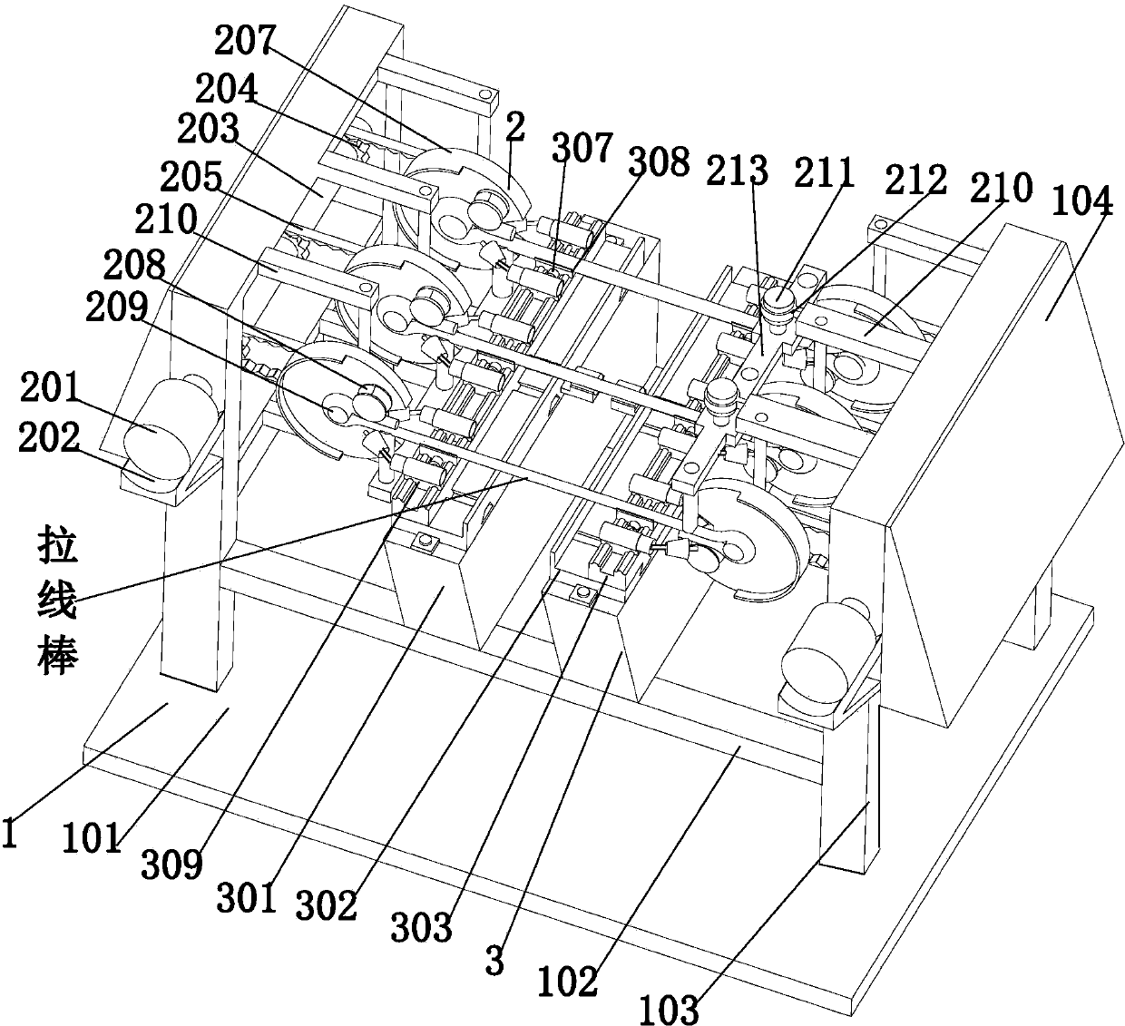
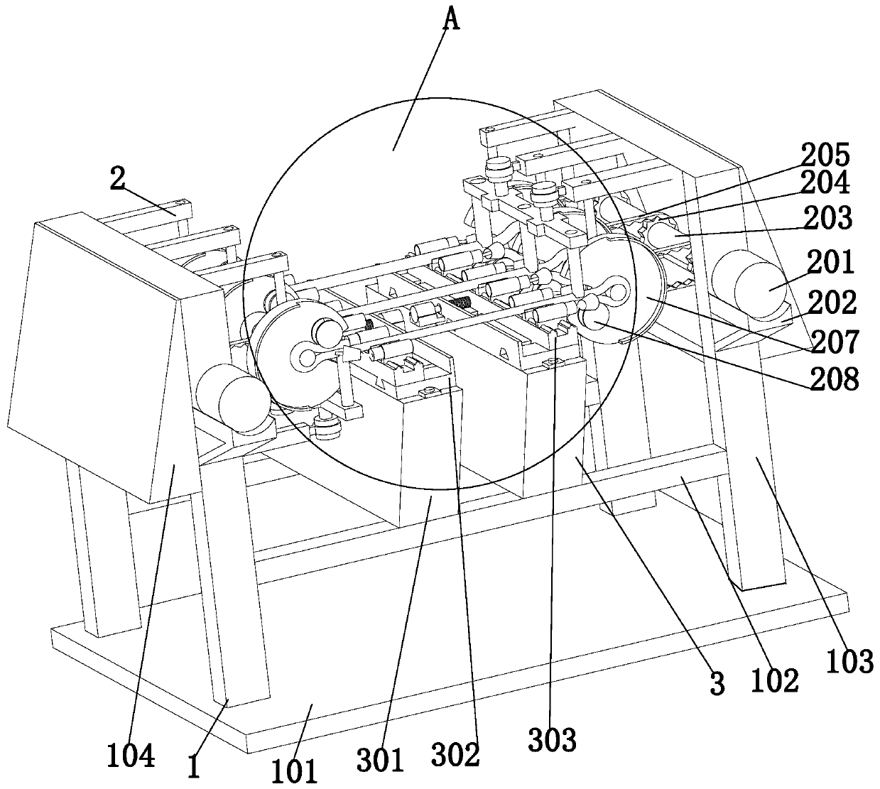
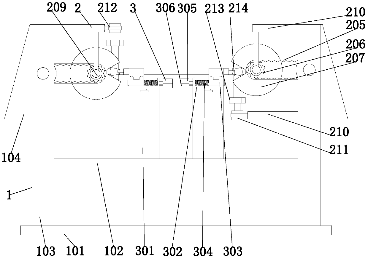
[0025] Such as Figure 1 to Figure 4 As shown, a forming auxiliary machine for making wire rods for power accessories and equipment includes a supporting mechanism 1, an actuator 2 and a welding mechanism 3. The supporting mechanism 1 is uniformly provided with an actuator 2, and the welding mechanism 3 is symmetrical Is installed on the supporting mechanism 1, and the welding mechanism 3 is located between the two sets of actuators 2; among them:

[0026] The supporting mechanism 1 includes a bottom plate 101, a transverse bracket 102, a column bracket 103, and a protective plate 104; a column bracket 103 is symmetrically installed on the bottom plate 101, and a protective plate 104 is installed on the outer wall of the column bracket 103, The ...


PUM


Abstract

The invention provides an auxiliary machine for manufacturing and forming an anchor rod for power accessory equipment. The auxiliary machine comprises a supporting mechanism, execution mechanisms andwelding mechanisms, wherein the execution mechanisms are uniformly arranged on the supporting mechanism; and the welding mechanisms are symmetrically arranged on the supporting mechanism and are located between the two groups of execution mechanisms. The auxiliary machine can solve the problems that an existing anchor rod mainly comprises a rod body and a pull ring; the pull ring is fixed to the top end of the rod body and is of an integrated structure with the rod body; during the specific production, firstly a round steel rod is cut out, then the top end of the round steel rod is bent into aclosed shape, and the joint parts of the ring body and the rod body are welded together through a welding gun to complete the production of the anchor rod; but the manufacturing and bending of the existing anchor rod are completed by a reinforcing steel bar bending and hooping machine, then a press machine is used for performing joint close, the welding gun is used for welding by a worker, therefore, the degree of automation is low, the continuity of manufacturing is poor, the working efficiency is low, and the production cost is high.

Description

Technical field [0001] The invention relates to the technical field of wire drawing rod forming and processing, in particular to a forming auxiliary machine for making wire drawing rods of electric power accessories. Background technique [0002] With the rapid development of the power industry, the use of transmission line poles is increasing. When planting the poles at the end of the line or the poles at the turns, in order to ensure the stability of the poles, it is often necessary to plant one in the opposite direction of the force. Or multiple adjustment cables, the cable rod is the necessary part to adjust the tension of the cable, [0003] The existing pull rod mainly includes a rod body and a pull ring. The pull ring is fixed on the top of the rod body and is an integral structure with the rod body. In the specific production, a round steel rod is first cut out and then the top end is bent into In a closed shape, the joint between the ring body and the rod body is welded t...

Claims


Application Information

Patent Timeline
Patent Type & Authority Applications(China)
IPC IPC(8): B23P23/00
CPCB23P23/00
Inventor 余佳瑞于陶瑞曹佳
Owner 马鞍山市华能电力线路器材有限责任公司
Why Eureka
Try Eureka