Automatic refractory brick material pouring and stamping device

A technology of punching device and refractory brick, applied in the direction of supply device, forming indenter, auxiliary forming equipment, etc., can solve the problems of complex production process, time-consuming and laborious, dust inhalation, etc., and achieve the effect of improving production efficiency

Active Publication Date: 2020-05-29
山东沈耐新材料科技有限公司
View PDF9 Cites 6 Cited by
  • Summary
  • Abstract
  • Description
  • Claims
  • Application Information

AI Technical Summary

Problems solved by technology

[0004] In order to overcome the fact that manual pouring will cause workers to inhale dust and powder, which is not conducive to the health of workers, it is also necessary to continuously pour powder into the feeding port, which is time-consuming and laborious. The production process is very complicated and the produ

Method used


Image

  • Automatic refractory brick material pouring and stamping device
  • Automatic refractory brick material pouring and stamping device
  • Automatic refractory brick material pouring and stamping device

Examples


Embodiment 1

[0023] A kind of refractory brick automatic pouring stamping device, such as Figure 1-4 As shown, it includes an operation table 1, a bottom plate 201, a fixed block 3, a transmission wheel 4, a material transport vehicle 5, a storage bin 6, a support block 7, a cylinder 8 and a pressing block 9, and the right part of the operation table 1 has a feeding Bottom plate 201 is provided at the bottom of port 2 and feed port 2, and two fixed blocks 3 are fixedly connected to operating platform 1, and fixed block 3 is located near the position of feeding port 2. Four transmission wheels 4 are installed on the material transport vehicle 5, a storage bin 6 is fixedly connected to the upper side of the left part of the operation platform 1, a support block 7 is fixedly connected to the rear side of the operation platform 1, and a cylinder is fixedly connected to the upper and lower sides of the support block 7 8. A pressure block 9 is fixedly connected to the lower end of the cylinder ...

Embodiment 2

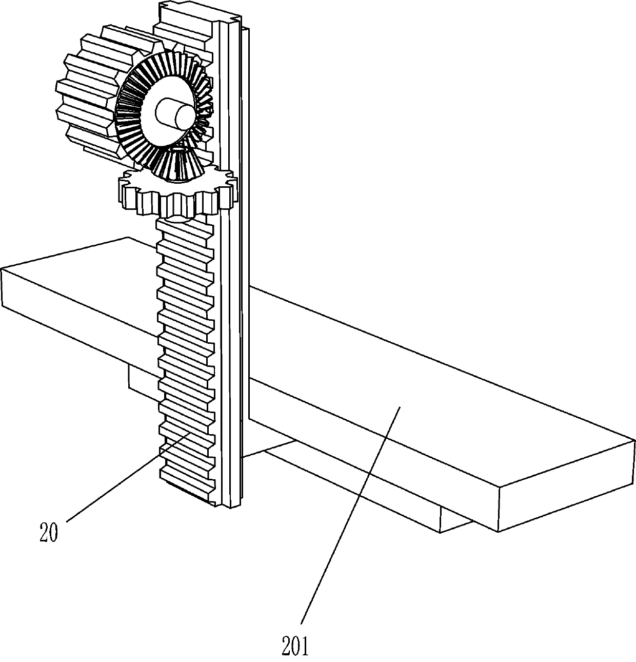
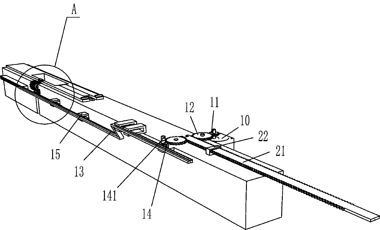
[0028] On the basis of Example 1, such as figure 2 As shown, it also includes a rotating motor 10, a second gear 11, a first gear 12, a third rack 21 and a fixed sleeve 22, and a rotating motor 10 is fixedly connected to the console 1 on the side away from the stamping mechanism. A second gear 11 is fixedly connected to the output shaft of the rotating motor 10, and two first gears 12 are rotatably connected to the console 1, and the first gear 12 on one side near the rotating motor 10 meshes with the second gear 11, A fixed sleeve 22 is fixedly connected to the operating table 1, and a third rack 21 is slid through the fixed sleeve 22. The third rack 21 meshes with the first gears 12 on both sides, and the first gear 12 at the rear Mesh with threaded gear 14.

[0029]Start the rotating motor 10, the rotating motor 10 drives the first gear 12 on the front side to rotate through the second gear 11, the first gear 12 drives the third rack 21, and the third rack 21 drives the f...

Embodiment 3

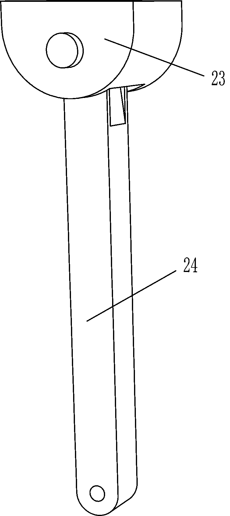
[0031] On the basis of Example 2, such as Figure 5-9 Shown, also comprise connecting block 23, rotating bar 24, fixed bar 25, pushing block 26, recessed block 27 and fixing plate 28, material delivery vehicle 5 lower sides are fixedly connected with connecting block 23, and connecting block 23 is hinged with rotating block. Rod 24, the left end of rotating rod 24 is hinged with the left end of the third rack 21, the right part of the material transport vehicle 5 is fixedly connected with a fixed rod 25, the right part of the fixed rod 25 is fixedly connected with a push block 26, and the upper side of the console 1 is fixedly connected with a concave Block 27, the upper side of the console 1 is fixedly connected with a fixed plate 28, and the concave block 27 is located in the middle of the fixed plate 28.

[0032] It also includes a slant plate 29, a support plate 2901, a trapezoidal block 30, a fixed shaft 31, a fitting plate 32 and a second spring 33. The upper side of the...


PUM


Abstract

The invention relates to an automatic material pouring and stamping device, and particularly relates to an automatic refractory brick material pouring and stamping device. The invention aims to provide the automatic refractory brick pouring and stamping device which can automatically pouring powder and automatically stamping and can also push out manufactured refractory bricks. The automatic refractory brick material pouring and stamping device comprises an operating table, a bottom plate, fixed blocks, transmission wheels, a material conveying vehicle, a storage bin, a supporting block and the like; a feeding port is formed in the operating table, the bottom plate is arranged in the feeding port, the two fixing blocks are fixedly connected to the operating table, the material conveying vehicle is placed in the operating table, and four transmission wheels are arranged on the material conveying vehicle. According to the automatic refractory brick material pouring and stamping device, apressure block is driven by an air cylinder to manufacture the refractory bricks, manual participation is not needed in the use process, and only the powder needs to be placed in the storage bin, sothat the raw materials can be automatically conveyed and poured.

Description

technical field [0001] The invention relates to an automatic dumping and stamping device, in particular to an automatic dumping and stamping device for refractory bricks. Background technique [0002] Refractory materials are generally divided into two types, namely unshaped refractory materials and shaped refractory materials. Unshaped refractories are also called castables, which are mixed powdery particles composed of various aggregates or aggregates and one or more binders. When used, they must be mixed with one or more liquids and stirred evenly. Strong mobility. Shaped refractory materials generally refer to refractory bricks, whose shape has standard rules, and can also be temporarily processed according to needs. Refractory bricks, referred to as firebricks for short, are refractory materials made of refractory clay or other refractory materials, light yellow or brownish, and are mainly used for building smelting furnaces. It can also be used as high-temperature b...

Claims


Application Information

Patent Timeline
IPC IPC(8): B28B3/04B28B13/02B28B17/00
CPCB28B3/04B28B13/02B28B13/0215B28B17/00
Inventor 不公告发明人
Owner 山东沈耐新材料科技有限公司
Why Eureka
Try Eureka