Food waste processor
A food waste treatment and electrical device technology, which is applied in indoor sanitary pipeline installations, water supply installations, buildings, etc., can solve problems such as motor burnt, metal parts rust, circuit board short circuit, etc., to prevent rust or corrosion, The effect of using a large space and improving the service life of the product
- Summary
- Abstract
- Description
- Claims
- Application Information
AI Technical Summary
Problems solved by technology
Method used
Image
Examples
Embodiment 1
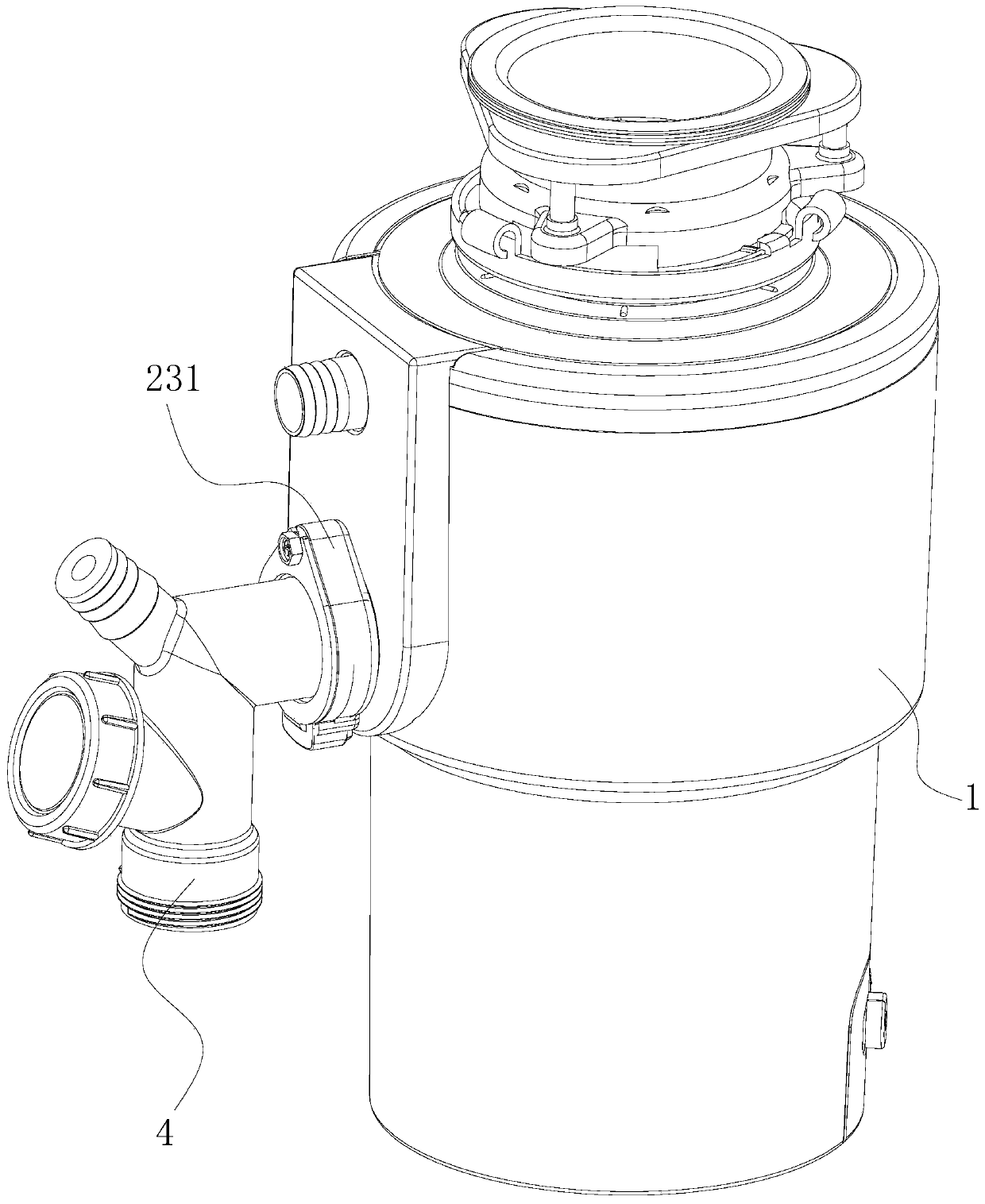
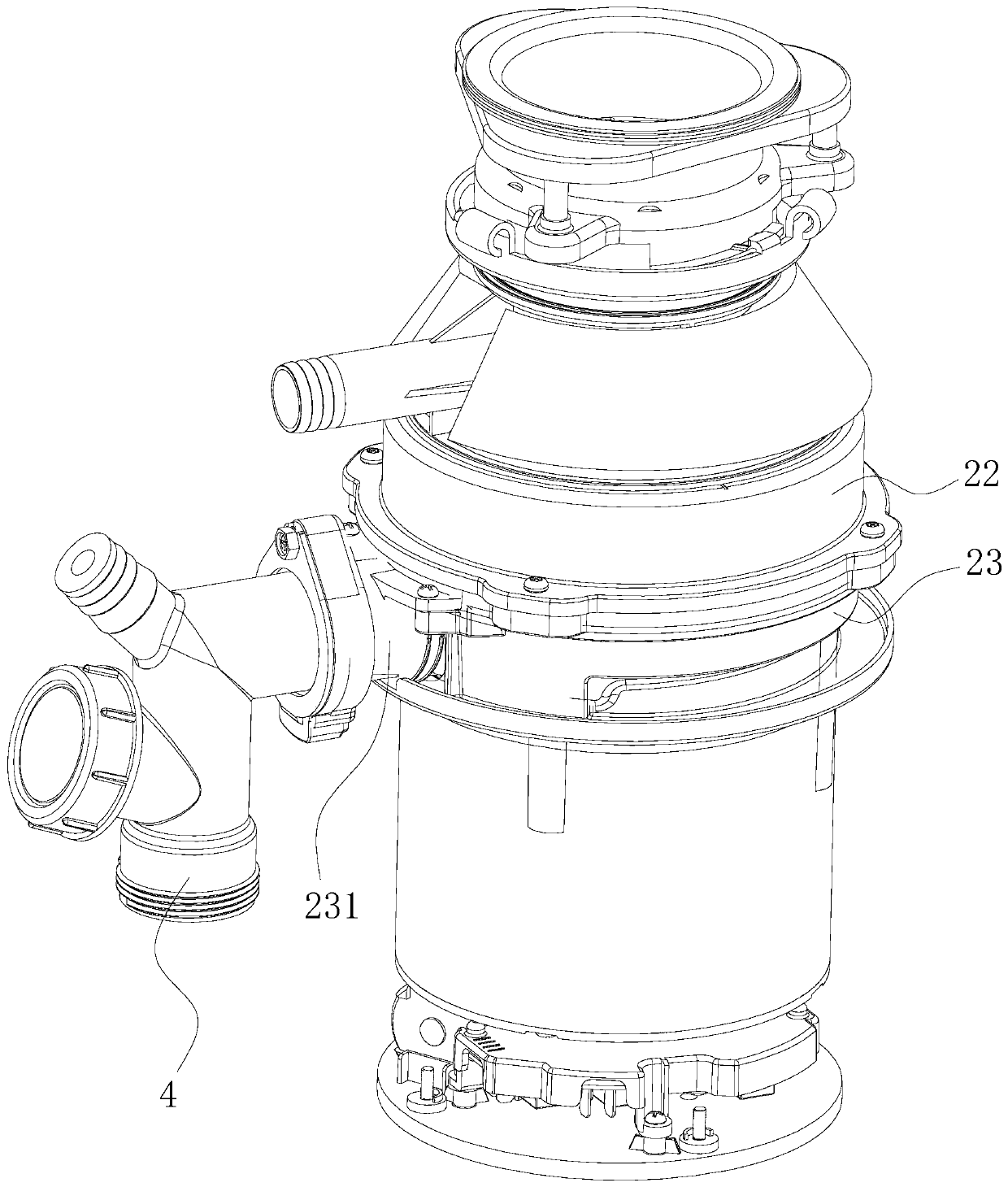
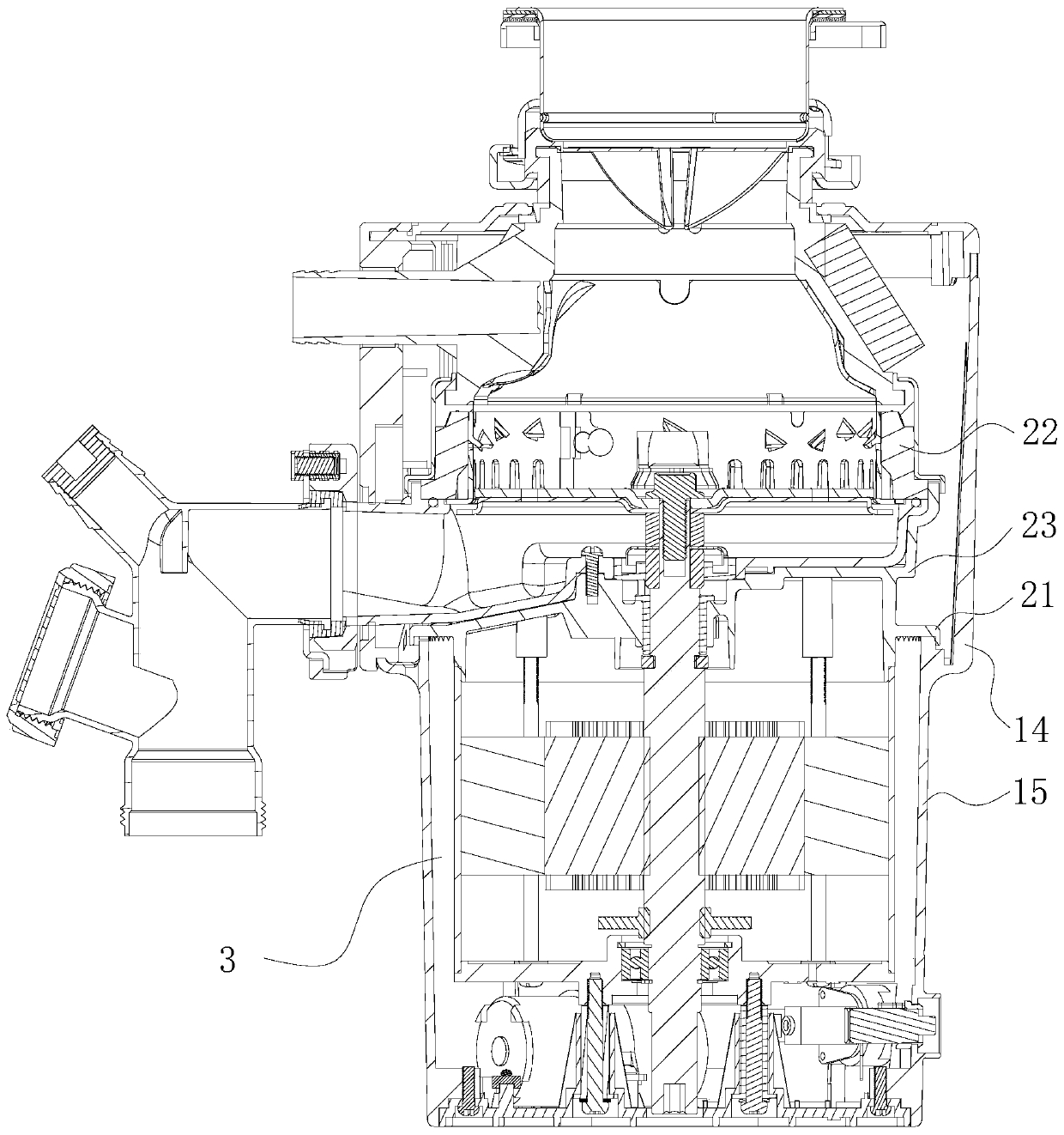
[0072] like Figure 1 to Figure 7 As shown, a food waste disposer includes a housing 1 and a motor end cover 23, the upper end of the housing 1 is provided with a grinding part 22, and the lower end of the housing 1 is provided with an accommodating space 3 ( Accommodating space 3 see details image 3 and Figure 5 ), the motor end cover 23 is located between the grinding part 22 and the accommodating space 3, and also includes a flow guide 21, a water collection tank 11 and a drainage structure, the flow guide 21 is arranged on the outside of the side wall of the motor end cover 23, and the water collection tank 11 Set on the inner side of the side wall of the housing 1, the sump 11 is located below the flow guide 21, the sump 11 is used to collect the liquid from the flow guide 21, and the drainage structure communicates with the sump 11 for the liquid in the sump 11 Drains to the outside of enclosure 1. Specifically, by setting the flow guide 21 and the water collection ...
Embodiment 2
[0081] The difference between this embodiment and Embodiment 1 is that the structure of the flow guide 21 is different. In this embodiment, as Figure 10 with Figure 11 As shown, the cross section of the flow guide 21 is "one" shape, and the end of the flow guide 21 away from the motor end cover 23 overlaps above the sump 11. The liquid is drained to the sump 11 . In this embodiment, a seal 5 is provided between the bottom of the flow guide 21 at the end away from the motor end cover 23 and the top of the side wall of the sump 11 near the motor end cover 23, and the seal 5 is used to block the liquid from moving along the guide. The bottom of the flow element 21 penetrates into the accommodation space 3 . Specifically, by providing the seal 5, it can be ensured that the liquid flows along the upper surface of the flow guide 21 to the end of the flow guide 21 away from the motor end cover 23, and cannot flow in reverse along the lower surface of the flow guide 21 to the end ...
Embodiment 3
[0084] The difference between this embodiment and Embodiment 1 is that the structural design of the flow guide 21 and the sump 11 is different. In this embodiment, as Figure 12 to Figure 15 As shown, the cross section of the flow guide 21 is "L" shape, the end of the flow guide 21 away from the motor end cover 23 is bent upward, and the bottom of the flow guide 21 is provided with a liquid-passing structure 213, which is used to The liquid in the deflector 21 is discharged to the sump 11 . By setting the upwardly bent deflector 21, the deflector 21 forms a similar water storage structure to collect the liquid, and then transfer the liquid to the water collection tank 11 through the liquid passing structure 213, and finally discharge it to the outside of the housing 1 , this design realizes the liquid collection on the motor end cover 23 itself, shortens the flow path of the liquid, and can improve the reliability of the liquid collection process and the discharge process. In...
PUM
 Abstract
Description
Claims
Application Information
 - R&D
- Intellectual Property
- Life Sciences
- Materials
- Tech Scout
- Unparalleled Data Quality
- Higher Quality Content
- 60% Fewer Hallucinations
Browse by: Latest US Patents, China's latest patents, Technical Efficacy Thesaurus, Application Domain, Technology Topic, Popular Technical Reports.
© 2025 PatSnap. All rights reserved.Legal|Privacy policy|Modern Slavery Act Transparency Statement|Sitemap|About US| Contact US: help@patsnap.com


