Drilling rod, drilling tool and pile machine

A technology for drill pipes and drilling tools, which is applied in the field of drilling tools, pile drivers, and drill pipes. It can solve problems such as low work efficiency, cumbersome operation process, and complex keyway shape, and achieve the effect of improving work efficiency and simple operation process.

Pending Publication Date: 2020-05-29
HAINAN ZHUODIAN HIGH TECH DEV +1
View PDF0 Cites 1 Cited by
  • Summary
  • Abstract
  • Description
  • Claims
  • Application Information

AI Technical Summary

Problems solved by technology

[0006] The object of the present invention is to provide a kind of drilling rod, drilling tool and pile driver, to alleviate the process of adjusting the position of the driving tube on the drilling rod in the existing drilling tool existing in the prior art, make the driving tube move more For a long distance, due to the complex shape of the keyway formed between the stepped bar splines, it is necessary to lift the drive tube on the drill pipe multiple times and make the drive tube rotate after lifting the drive tube. The operation process is cumbersome , technical issues that lead to lower productivity

Method used


Image

  • Drilling rod, drilling tool and pile machine
  • Drilling rod, drilling tool and pile machine
  • Drilling rod, drilling tool and pile machine

Examples


Embodiment 1

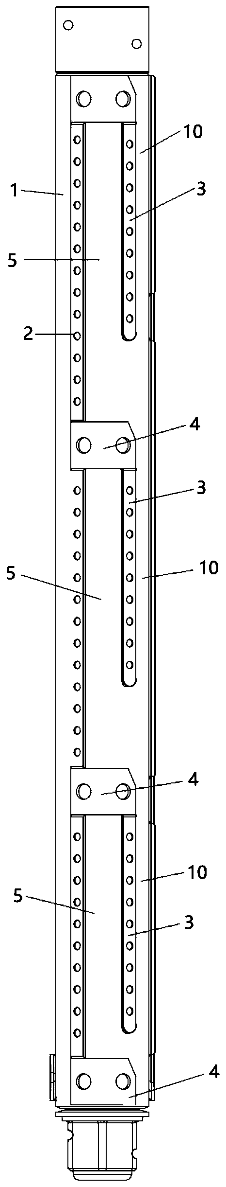
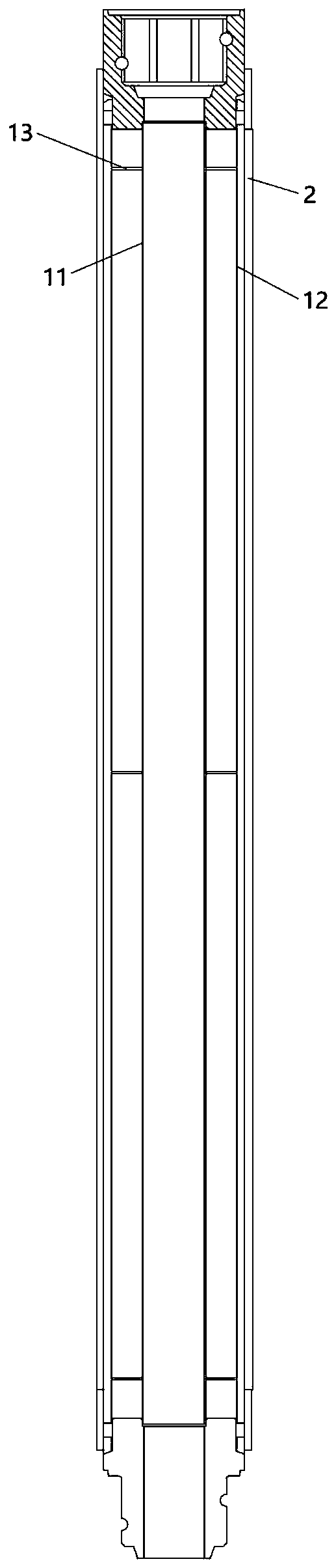
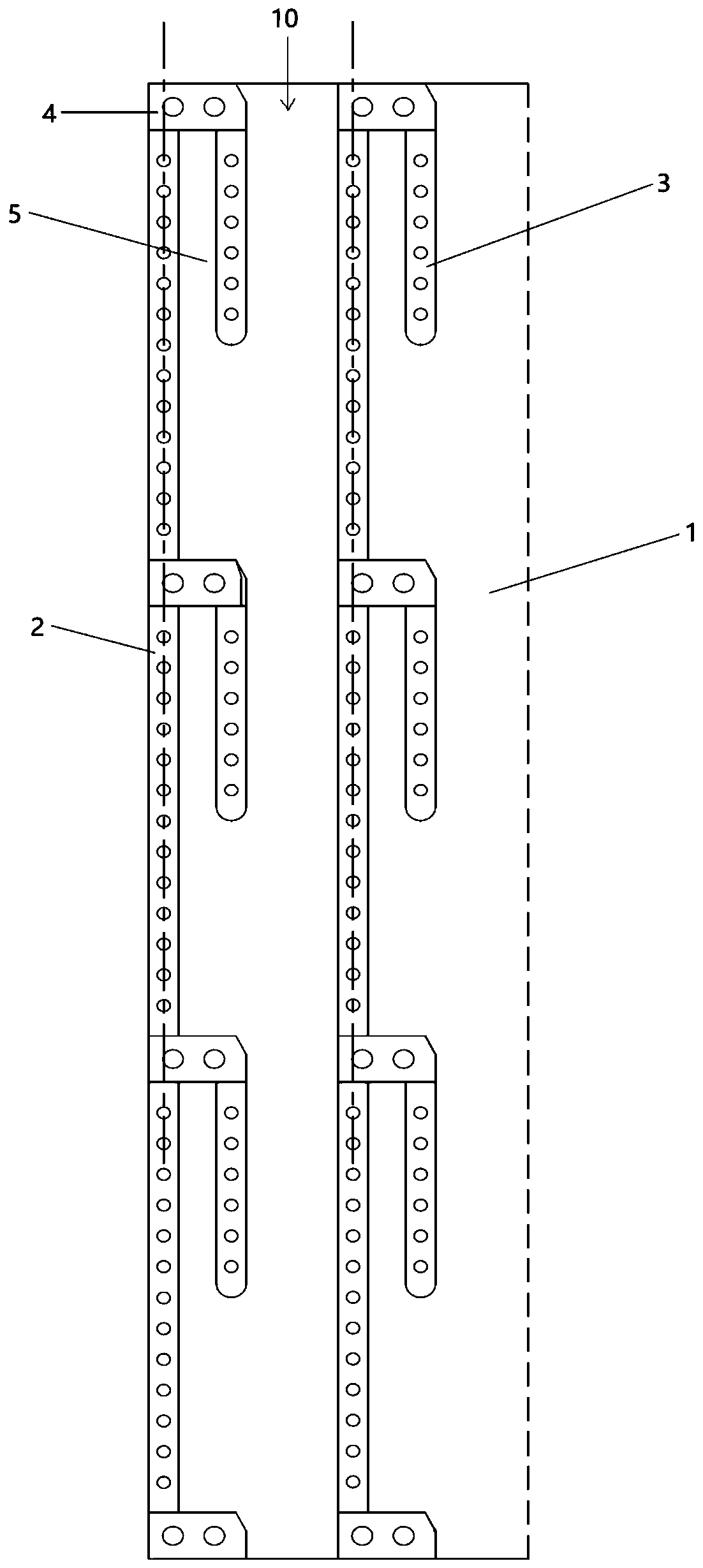
[0037] Such as Figure 1-Figure 4 As shown, the drill pipe provided in this embodiment includes a hollow driven rod 1, and the driven rod 1 is provided with a limit key group. The limit key group includes an inline first limit key 2, a plurality of inline first limit keys Two limit keys 3 and a plurality of stoppers 4. The first limit key 2 is arranged on the driven rod 1 along the axial direction of the driven rod 1, and a plurality of second limit keys 3 are arranged on the driven rod 1 at intervals along the axial direction of the driven rod 1 and are located on the first The same side as limit key 2. The distance between two adjacent second limit keys 3 is not less than the length of the convex key 60 on the inner wall of the power tube 6 in the drill bit.

[0038]A stopper 4 is connected between each second limit key 3 and the first limit key 2, and the stopper 4 is used to form a The limit groove 5 is used to accommodate the convex key 60 on the inner wall of the powe...

Embodiment 2

[0065] The drilling tool provided in this embodiment includes the power head and the drill rod in the first embodiment. The power head includes a power tube. The inner wall of the power tube is provided with a bar-shaped convex key. The power tube is sleeved on the driven rod in the drill pipe. The convex key on the inner wall of the power tube can pass through two adjacent After the interval between the second limiting grooves is located in the limiting grooves.

[0066] Wherein, the power tube is used to drive the driven rod to rotate by its own rotation.

[0067] Further, grooves may be provided on the inner wall of the power tube, and the strip-shaped convex keys may be embedded in the grooves and fixed in the grooves by screws.

[0068] Further, a protrusion can be provided in the groove bottom of the groove on the inner wall of the power tube, and a dovetail groove corresponding to the above protrusion can be provided at the position of the bar-shaped protrusion key cor...

Embodiment 3

[0072] The pile driver provided in the present embodiment includes the drilling tool in the second embodiment, and the pile driver provided in the present embodiment can solve the same technical problem as the drilling tool in the second embodiment and achieve the same technical effect.

[0073] Therefore, the pile driver provided by this embodiment also alleviates the process of adjusting the position of the drive tube on the drill rod in the existing drilling tool in the prior art, and when the drive tube is moved for a long distance, due to the stepped The shape of the keyway formed between the bar splines is complex, so it is necessary to lift the drive tube on the drill pipe multiple times and make the drive tube rotate after lifting the drive tube. The operation process is cumbersome, resulting in low work efficiency. technical problem.


PUM


Abstract

The invention provides a drilling rod, a drilling tool and a pile machine, and relates to the technical field of construction machines. The drilling rod comprises a hollow driven rod. Limiting key sets are arranged on the driven rod and each comprise a linear first limiting key, multiple linear second limiting keys and multiple stop parts. The first limiting keys are arranged on the driven rod inthe axial direction of the driven rod. The multiple second limiting keys are arranged on the driven rod at intervals in the axial direction of the driven rod and are located on the side the same as the first limiting keys. The interval between every two second limiting keys is not smaller than the length of a convex key on the inner side wall of a power pipe in a power head of the drilling tool. One corresponding stop part is connected between each second limiting key and the corresponding first limiting key. According to the drilling rod, the drilling tool and the pile machine, the technicalproblems that in the prior art, in the process of adjusting the position of a drive pipe on the drilling rod, when the drive pipe is moved by a long distance, the operation that the drive pipe ascendsand descends on the drilling rod many times and is made to achieve autorotation after ascending and descending needs to be carried out, and the operation process is complex are relieved.

Description

technical field [0001] The invention relates to the technical field of construction machinery, in particular to a drill pipe, a drill tool and a pile driver. Background technique [0002] Pile driver is a relatively commonly used pile foundation construction equipment. Drilling tools are installed in the pile driver, and the drilling tools include setting drill pipes and power heads. The power head is used to apply torque to the drill pipe, and the pile driver also includes an axial force drive assembly, which is used to apply axial load to the drill pipe. [0003] Since the bottom of the drill rod is provided with helical blades, the power head of the drilling tool is usually installed on the top of the drill rod in order not to hinder the use of the drill rod. But because the power head is heavy, the power head is installed on the top of the drill pipe, which will lead to poor stability of the drilling tool, and in the process of drill pipe rotation, it is easy to cause c...

Claims


Application Information

Patent Timeline
IPC IPC(8): E21B17/00E21B17/22E21B17/046
CPCE21B17/00E21B17/046E21B17/22
Inventor 彭樱彭桂皎谭燕姬陈海同
Owner HAINAN ZHUODIAN HIGH TECH DEV
Why Eureka
Try Eureka