
Integrated heat exchanger

A heat exchanger, an integrated technology, applied in the direction of heat exchange equipment, heat exchanger type, heat exchanger shell, etc., can solve the problems of reducing assembleability, deformation, separation of gasket 15, etc., and achieves the improvement of assembleability. Effect

Inactive Publication Date: 2020-05-29
HANON SYST
View PDF8 Cites 0 Cited by
  • Summary
  • Abstract
  • Description
  • Claims
  • Application Information

AI Technical Summary

Problems solved by technology

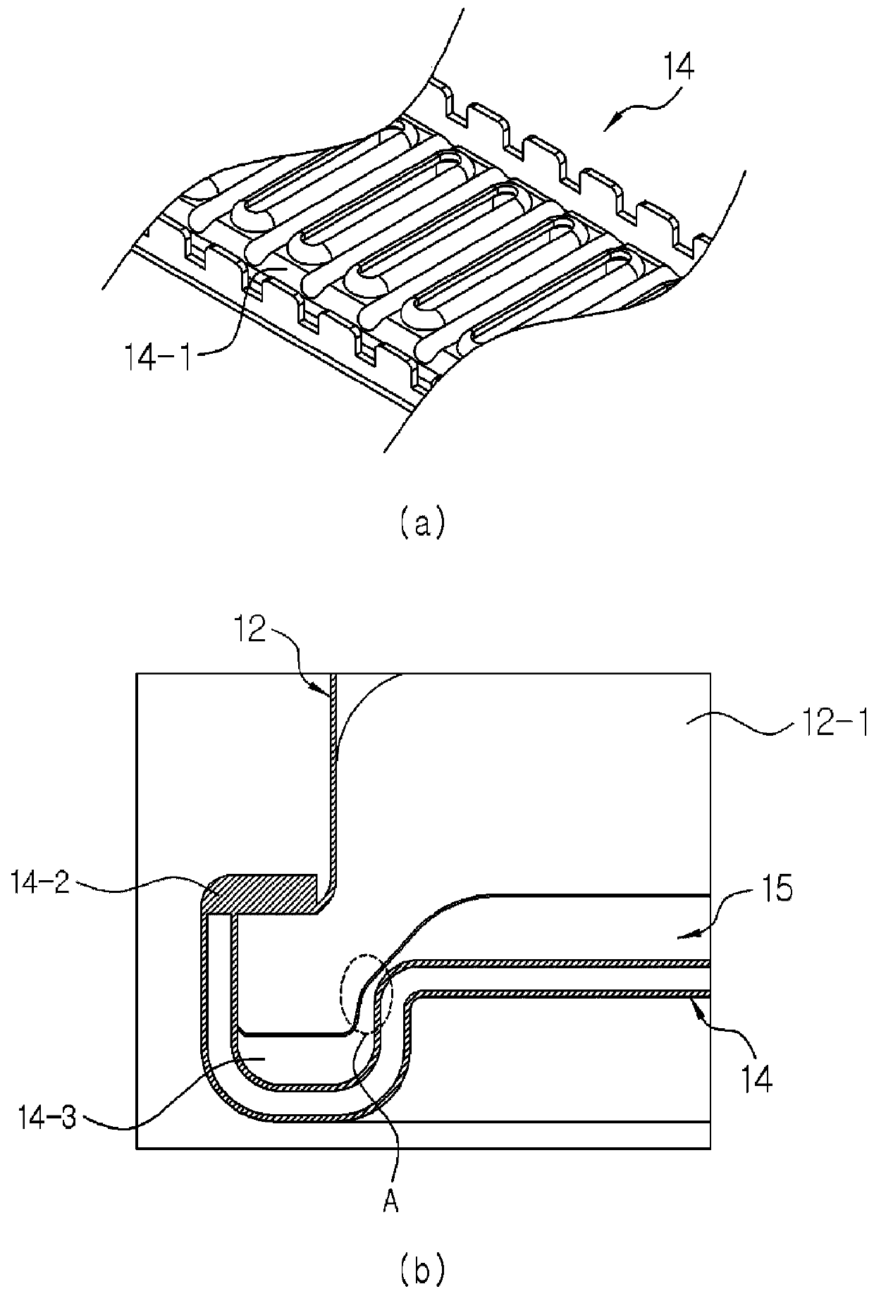
[0004] However, the prior art header tank 11 has a problem that when the tank 12 and the header 14 are coupled, the gasket 15 located at the isolation area 16 is pulled and deformed
In detail, such as figure 2 As shown in (b), when the box 12 and the header pipe 14 are connected by bending the bending member 14-2 formed at the edge of the header pipe 14, it is located in area A (in area A, formed at the header pipe 14 The gasket 15 in the groove 14-1 connected to the coupling recess 14-3 of the tank 12) is pulled and deformed due to the coupling force of the tank 12 and the header 14, and therefore, the gasket 15 may be out of position or damaged
[0005] In addition, the gasket 15 used when coupling the header tank 11 of the prior art is designed so that its edge fitted into the coupling recess 14-3 has a circular cross-sectional shape and its part of the sealing tank baffle 12-1 has a quadrangular shape. The cross-sectional shape, therefore, changes the degree of compression of the gasket in response to external forces, reducing assemblability
In other words, even if the material is the same, depending on its shape, the degree of compression in response to external force is different, in particular, because the degree of compression of the quadrilateral cross-section is smaller than that of the circular cross-section, so if you want to compress the quadrilateral cross-section part and the circle In order to have the same compression ratio, the quadrilateral cross-section part needs to have a larger compressive force than the circular cross-section part, resulting in the following problem: Unnecessarily stronger force is required to assemble the tank 12 and header 14

Method used


Image

  • Integrated heat exchanger
  • Integrated heat exchanger
  • Integrated heat exchanger

Examples


Embodiment Construction

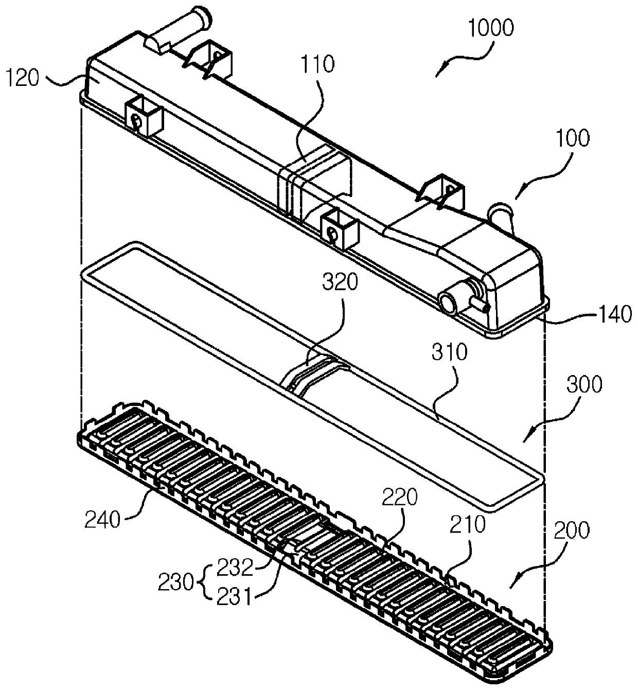
[0026] In the integrated heat exchanger of the present invention in which a header tank is attached to both ends of a plurality of heat exchange tubes, the header tank includes: a tank 100 to which the first heat exchange medium and the second heat exchange medium are supplied; tube 200, the header 200 is connected to the heat exchange tube; and a gasket 300, which is inserted between the tank 100 and the header 200, wherein a tank baffle 110 is installed in the tank to separate the first heat exchange medium and the second heat exchange medium medium, the gasket 300 includes a baffle seal portion 320 disposed at a portion in contact with the tank baffle 110, the header 200 includes a support surface 230 disposed at a portion in contact with the baffle seal portion 320, and the support surface 230 includes a height The inclined surface 231 decreases towards the outside of the header 200 .

[0027] In addition, the support surface 230 has a flat seating surface 232 connected to...


PUM


Abstract

The present invention relates to an integrated heat exchanger in which a flow path, in which a first heat exchange medium flows, and a flow path, in which a second heat exchange medium flows, are separated by means of a baffle. The integrated heat exchanger of the present invention has: a support surface having a slope of which the height lowers toward the outside, and formed at a header portion coming in contact with a gasket baffle sealing part, and the gasket baffle sealing part formed in a shape corresponding to the support surface of a header such that the deformation of a gasket can be prevented when a tank and the header of a header tank are coupled, and a problem in which the gasket of a coupling part, at which the baffle is positioned, is non-uniformly compressed or the gasket isbroken or separated from a designated position by means of force of the other direction is prevented, and thus the sealing performance of the header tank can be more improved.

Description

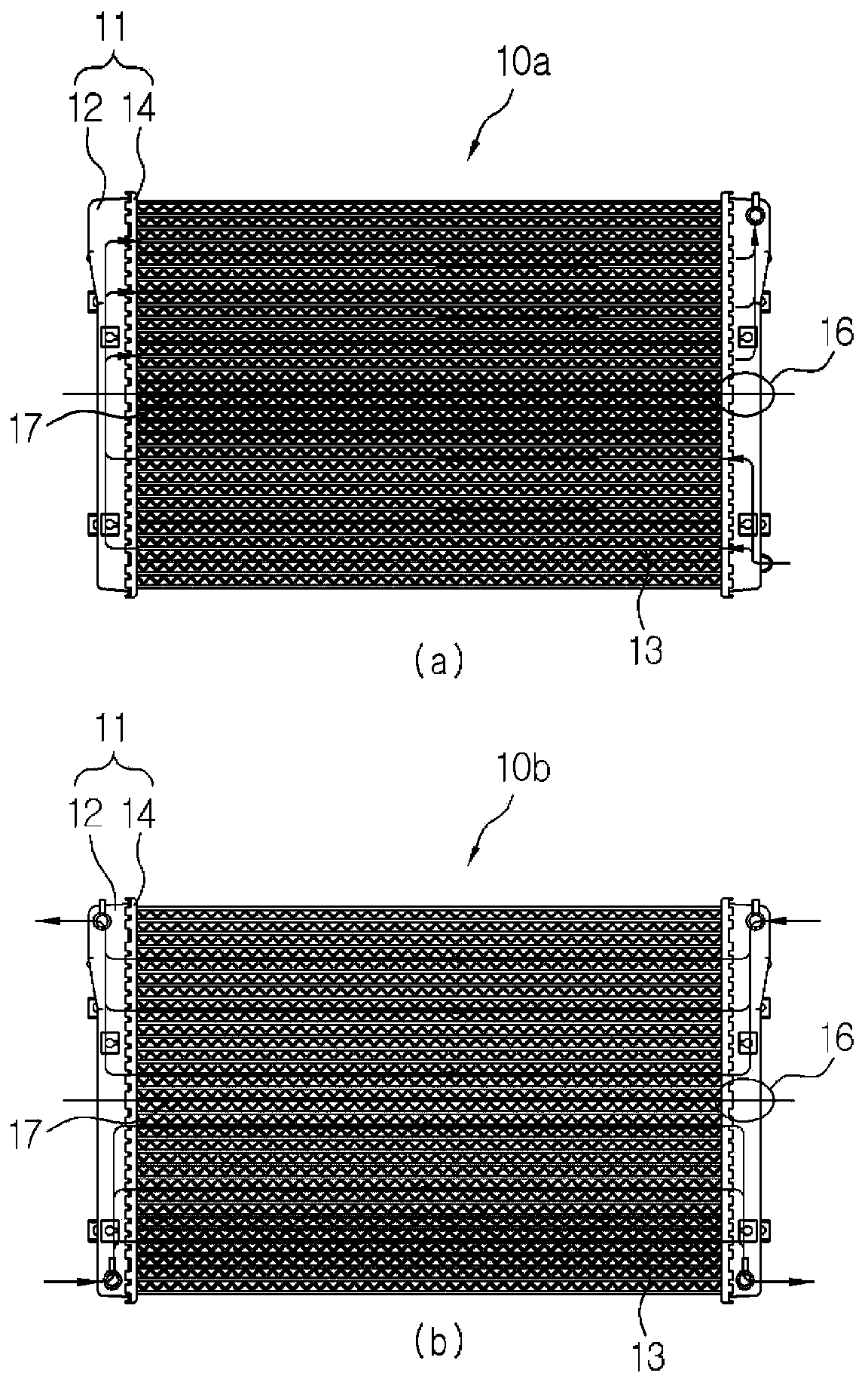
technical field [0001] The present invention relates to a heat exchanger, and more particularly to an integrated heat exchanger in which a flow path through which a first heat exchange medium flows and a flow path through which a second heat exchange medium flows are separated by a baffle . Background technique [0002] A heat exchanger having separate coolant flow paths in a single radiator to improve the heat exchange performance of the radiator has been actively studied, for example, a radiator such as the U-flow type radiator 10a has been developed device in which the flow path for introducing coolant and the flow path for discharging coolant are separated from each other (eg figure 1 (a)); or a low-temperature / high-temperature integrated radiator 10b in which coolants having different temperatures have separate flow paths (such as figure 1 shown in (b)). [0003] The header tank 11 of the U-shaped-flow type radiator 10a or the low-temperature / high-temperature integra...

Claims


Application Information

Patent Timeline
Patent Type & Authority Applications(China)
IPC IPC(8): F28F9/02F28F9/22F28F9/16F28D21/00
CPCF28F9/0214F28F9/22F28F9/04F28F11/02F28F2009/224F28D1/0443F28D1/05375F28F9/0209F28F9/0212F28F9/0226F28F2270/02F28D1/05366
Inventor 崔正范高光玉赵柄善韩至勋
Owner HANON SYST
Learn More