Cavity internal screw automatic press fitting equipment

An internal screw and automatic technology, which is applied in metal processing equipment, assembly machines, metal processing, etc., can solve problems such as uneconomical, unguaranteed quality, and high pressure, and achieve the effects of convenient production, reduced beat impact, and large scalability

Pending Publication Date: 2020-06-02
苏州托克斯冲压设备有限公司
View PDF0 Cites 0 Cited by
  • Summary
  • Abstract
  • Description
  • Claims
  • Application Information

AI Technical Summary

Problems solved by technology

[0003] This form is limited by the structure of the elongated pressure block, and both ends need to bear force. At the same time, because the screws will be embedded in the material during the press-fitting process, the workpiece will sink as a whole. If one side is press-fitted (not two points together), the material on the left side will sink and be embedded in the material, which will cause the material on the right side to deform, which will lead to the overall deformation of the workpiece.
If press-fitting at the same time, there will also be the following disadvantages: too much pressure, uneconomical, poor equipment expansion, because two simultaneous press-fitting, the pressure displacement process of a single screw cannot be accurately monitored, and the quality cannot be guaranteed

Method used


Image

  • Cavity internal screw automatic press fitting equipment
  • Cavity internal screw automatic press fitting equipment
  • Cavity internal screw automatic press fitting equipment

Examples


Embodiment Construction

[0030] The preferred embodiments of the present invention will be described in detail below in conjunction with the accompanying drawings, so that the advantages and features of the present invention can be more easily understood by those skilled in the art, so as to define the protection scope of the present invention more clearly.

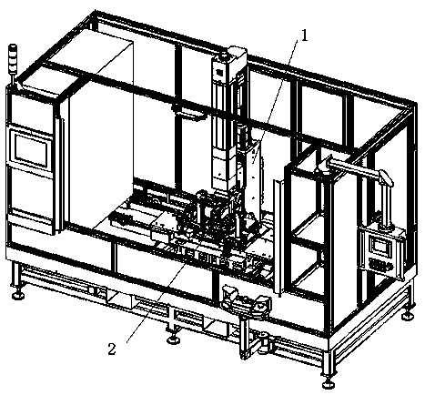
[0031] See attached image 3 to attach Figure 9 , with image 3 It is a perspective view of the screw automatic press-fitting device in the cavity according to the present invention, with Figure 4 The working surface of the modular design of the screw automatic press-fitting equipment in the cavity according to the present invention is described, and the attached Figure 5 It is described that the screw automatic press-fitting equipment in the cavity according to the present invention switches the working surface of the tooling assembly, and the attached Figure 6 The side view of the tooling assembly is switched for the automatic screw pres...


PUM


Abstract

The invention relates to cavity internal screw automatic press fitting equipment. The cavity internal screw automatic press fitting equipment comprises a machine body, a table top, a floating plier body assembly, a tool assembly, and a plier body supporting block, wherein the floating plier body assembly is connected with the machine body, and is provided with a C-shaped pressure head; the tool assembly is arranged below the floating plier body assembly, and is connected with the table top; the tool assembly is provided with a circular force bearing block; the circular force bearing block is provided with a rotating shaft; the rotating shaft is connected to a rotary cylinder; a first floating block is arranged on the circular force bearing block; a lower mold is arranged on the first floating block; a workpiece press-fitting hole allowing a workpiece to be accommodated is formed in the lower mold; a lower side force bearing block which corresponds to the first floating block is arranged below the disc force bearing block; and the plier body supporting block is arranged below the lower side force bearing block. The cavity internal screw automatic press fitting equipment disclosed bythe invention is large in expansibility, and putting into production and increasing of the later stage products are convenient; and besides, automatic press fitting and process monitoring of a plurality of screws are realized; and the cavity internal screw automatic press fitting equipment is also suitable for press fitting of other cavity type section material spare parts, and a series of stepsof single-time feeding, automatic pressing in, process monitoring and the like are realized.

Description

technical field [0001] The invention relates to an automatic press-fitting device for screws in a cavity. Background technique [0002] See attached figure 1 As shown, in the automatic press-fitting process of the cavity-like parts shown in the figure, two screws are manually loaded into the cavity at a time, and then the equipment is automated to realize the press-fitting process. The tooling needs to be designed in a modular manner to switch other tooling as a whole . See attached figure 2 The press-in process of screws and plates shown, for this type of workpiece, the existing common practice is to insert a long strip of pressure block between the cavity upper layer material and the cavity lower layer material in the cavity of the part as a whole load bearing On the other hand, when pressing, the forming die will squeeze the plate to form a pit so that the screw can be embedded, and the screw is pressed into the slightly smaller hole of the plate to achieve material e...

Claims


Application Information

Patent Timeline
IPC IPC(8): B23P21/00B23P19/027
CPCB23P21/004B23P19/027B23P19/001B23P19/007
Inventor 刘礼丰阮辉王明罡
Owner 苏州托克斯冲压设备有限公司
Why Eureka
Try Eureka