High-temperature high-speed jet deflection device

A high-speed jet and deflection device technology, which is applied to jet propulsion devices, rocket engine devices, machines/engines, etc., can solve problems such as large civil engineering, equipment investment burden, increased water spray area, and failure to carry out swing tests, etc., to achieve equipment investment Effects of light load, small aerodynamic loss, and low drag coefficient

Inactive Publication Date: 2020-06-02
BEIJING INST OF AEROSPACE TESTING TECH
View PDF12 Cites 2 Cited by
  • Summary
  • Abstract
  • Description
  • Claims
  • Application Information

AI Technical Summary

Problems solved by technology

[0005] The technology of the present invention solves the problem: at present, the method of increasing the water spray area, the number of water pumps, and the volume of the pool is adopted when the existing ground test bench tests the engine that swings at a large angle, which causes a huge civil engineering and equipment investment burden, while the high-altitude simulation test bench The upper swing test cannot be carried out

Method used


Image

  • High-temperature high-speed jet deflection device
  • High-temperature high-speed jet deflection device
  • High-temperature high-speed jet deflection device

Examples


Embodiment Construction

[0014] The present invention will be described in detail below in conjunction with the accompanying drawings and specific embodiments.

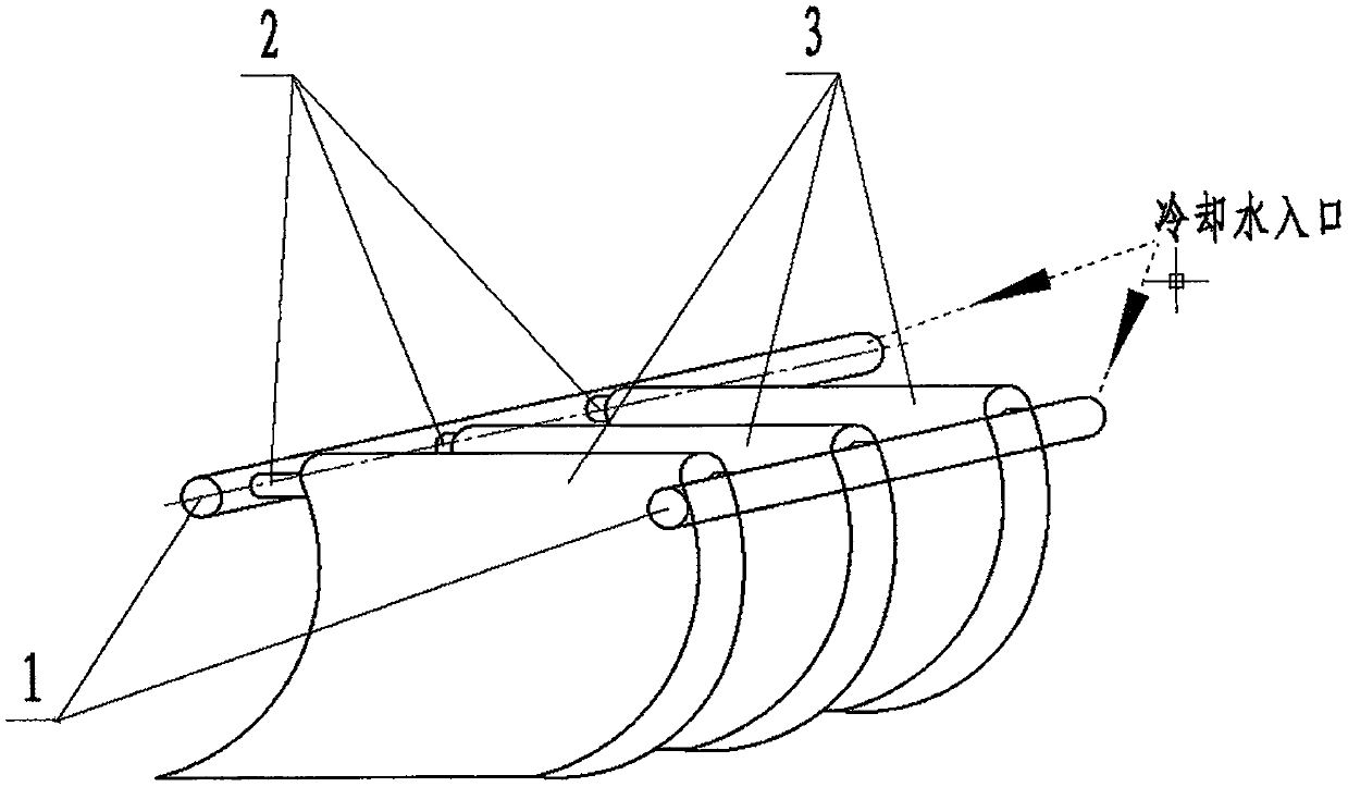
[0015] A high-temperature high-speed jet deflection device is characterized in that the device is composed of a main flow pipe 1, a branch flow pipe 2, and a guide vane array 3; the main flow pipe 1, the branch flow pipe 2, and the guide vane array 3 are all made of powder alloy and There is a flow path inside; the main flow pipe 1 is used to support the branch pipe 2 and the guide vane array 3; water.

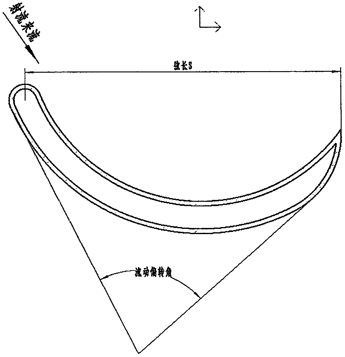
[0016] The implementation of the invention first determines the diameter D of the nozzle outlet of the engine that needs to be tested e , velocity Ue and pressure Pe, determine the aerodynamic parameters at the installation position of the jet deflection device, determine the wall thickness requirements of each guide vane in the main flow pipe 1, branch pipe 2, and blade array 3; secondly, determine the guide vane according to the size of th...


PUM


Abstract

The invention provides a high-temperature high-speed jet deflection device. The high-temperature high-speed jet deflection device is characterized by comprising a main flow tube 1, branch flow tubes 2, and a guide vane array 3; the main flow tube 1, the branch flow tubes 2 and the guide vane array 3 are all made of powder alloy and are internally provided with flow paths that communicate; the mainflow tube 1 is used for supporting the branch flow tubes 2 and the guide vane array 3; and the main flow tube 1 is connected to a cooling water pipeline and transports the sweat cooling water to thebranch flow tubes 2 and the guide vane array 3. The device can be used for the thermal protection of a ground test bench structure in the engine swing test, and can also be used for the thermal protection of an exhaust system in the engine swing test on a high altitude simulation test bed.

Description

technical field [0001] The invention relates to a sweat-cooled cascade-type airflow deflection device, which can change the flow direction of high-temperature and high-speed jets, and is mainly used for thermal protection of rocket engine ground test benches and high-altitude simulation test benches. Background technique [0002] During the development and test of a large liquid rocket engine, the swing test is an important test content to investigate the performance of the engine. Regardless of whether the engine adopts the pump-swing scheme or the pump-swing scheme, the supersonic high-temperature (up to 3800K) jet discharged from the engine nozzle will swing within a certain angle (usually 0-10°) during the test, which will cause In some non-swing tests, structural load-bearing parts with very low mechanical and thermal loads are directly scoured by high-temperature and high-speed jets, which may cause ablation damage or even endanger the structure of the test bench. Espe...

Claims


Application Information

Patent Timeline
Patent Type & Authority Applications(China)
IPC IPC(8): F02K9/96F02K9/60F02K9/64
CPCF02K9/96F02K9/60F02K9/64
Inventor 赵宏敖春芳李斌
Owner BEIJING INST OF AEROSPACE TESTING TECH
Why Eureka
Try Eureka