Protein staple fiber testing device
A testing device and short fiber technology, applied in measuring devices, using stable tension/pressure to test the strength of materials, instruments, etc., can solve the problem of fiber bundle slippage, can not meet the testing requirements of protein short fibers, and short fibers cannot be used for strong elongation. test, etc.
- Summary
- Abstract
- Description
- Claims
- Application Information
AI Technical Summary
Problems solved by technology
Method used
Image
Examples
Embodiment 1
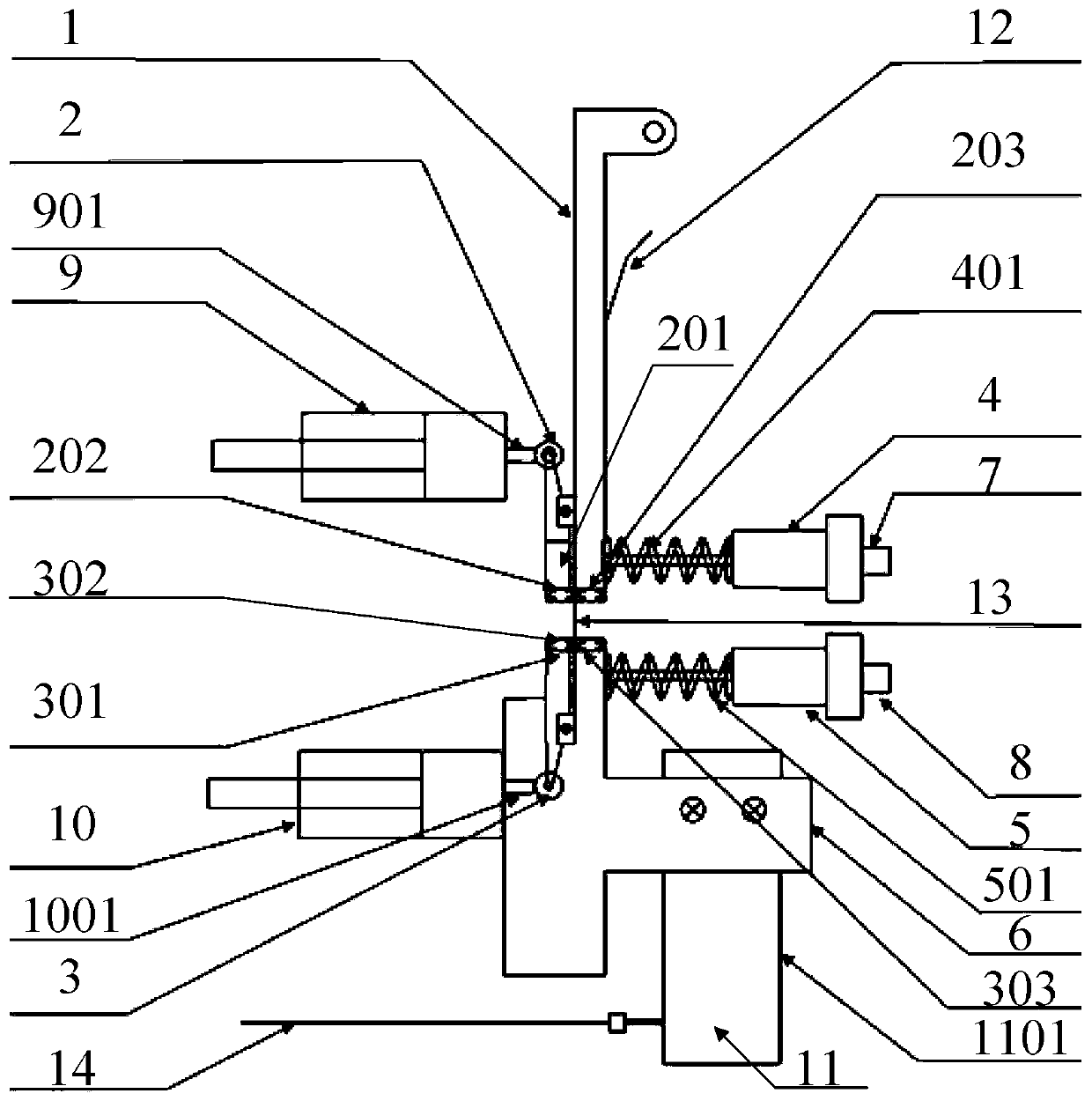
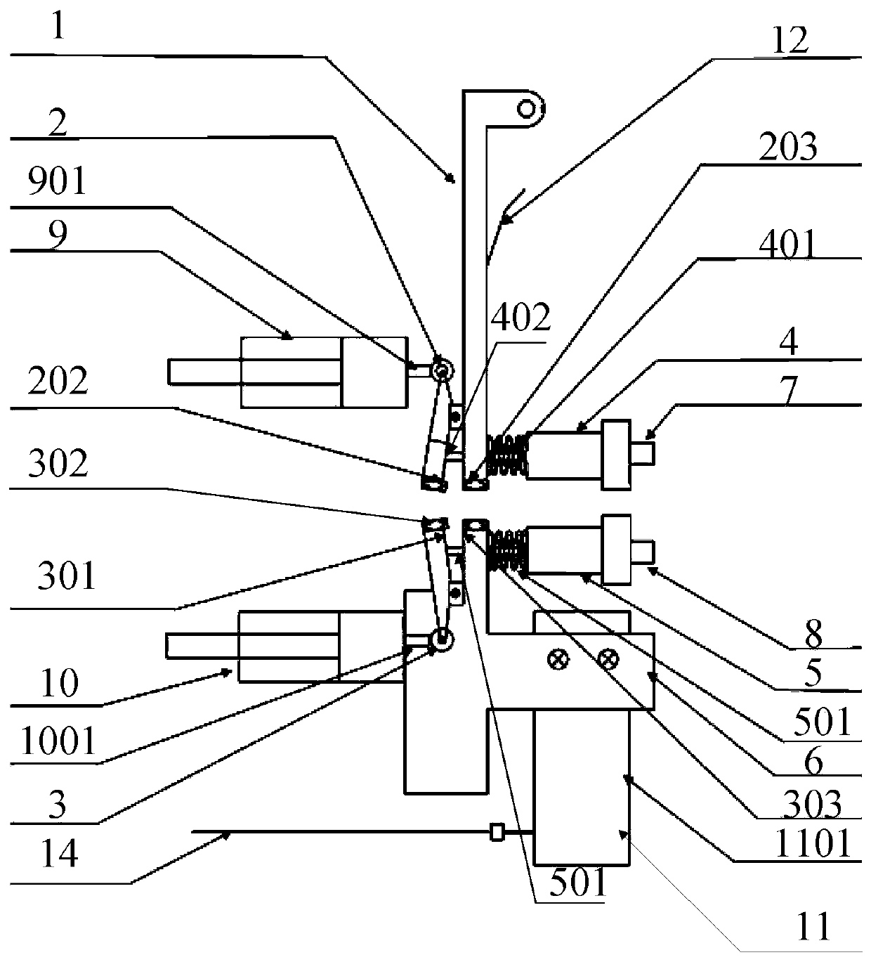
[0058] The present invention provides a device suitable for protein short fiber testing. Among them, the device suitable for protein short fiber testing includes a load sensing connection device 1 , an upper clamping device 2 , a lower clamping device 3 , an upper clamping force control device 4 and a lower clamping force control device 5 .
[0059] The upper clamping device 2 is installed on the load-sensing connection device 1, and the load-sensing connection device 1 is connected with the tension sensor. It should be noted that the connection method between the load-sensing connection device 1 and the tension sensor can be any way. Disassembly and assembly, the present invention discloses that the load sensing connecting device 1 and the tension sensor are detachably connected, and the load sensing connecting device 1 is connected with the tension sensor by interference fit, that is, the metal rod of the tension sensor is connected to the load sensing connecting device 1. m...
Embodiment 2
[0064] In the second embodiment provided by the present invention, the structure of the test device suitable for short protein fibers in this embodiment is similar to that of the test device for short protein fibers in the first embodiment, and the similarities will not be repeated here. Only the differences are described.
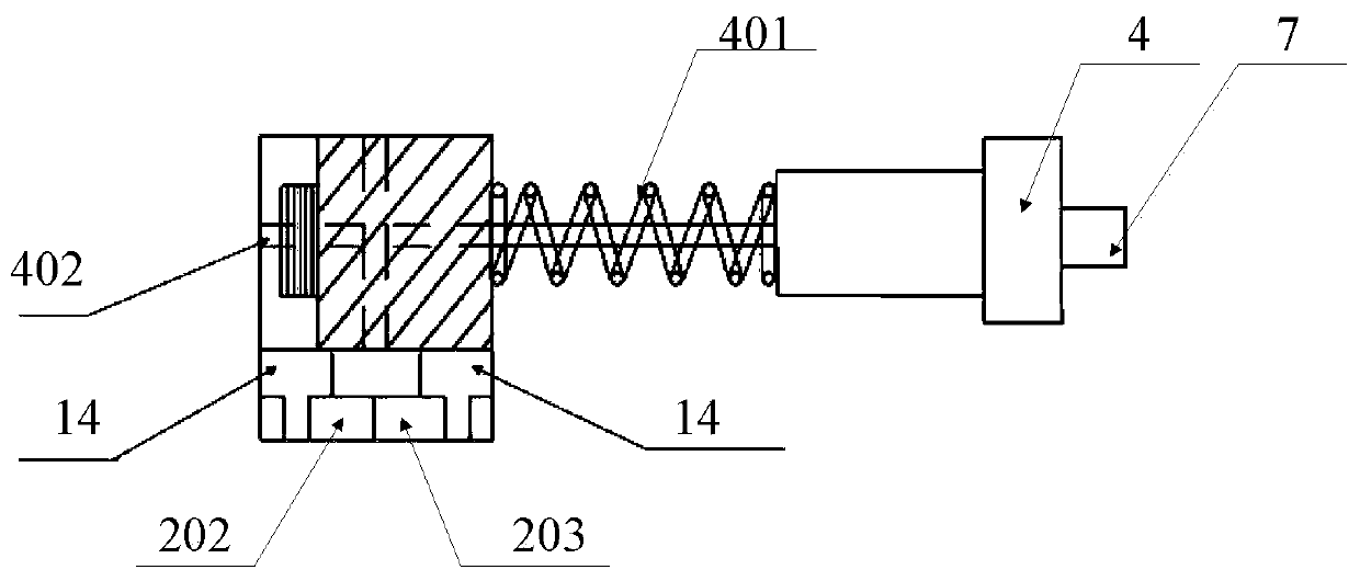
[0065] In this embodiment, the present invention specifically discloses that the upper clamping device 2 includes a first pressing rod 201, a first clamping piece 202 and a second clamping piece 203, the load sensing connecting device 1 is provided with a first fulcrum seat, A pressing rod 201 is hinged on the first fulcrum seat, and the clamping end of the first pressing rod 201 is connected to the first clip 202 . The second clip 203 is fixed on the load sensing connection device 1, and the upper clip force control device 4 is connected to the first clip 202, and can control the clamping force between the first clip 202 and the second clip 203, The firs...
Embodiment 3
[0092] The present embodiment uses the short protein fiber testing device provided in embodiment two to carry out the test, and the specific embodiment takes 3.0mm hair short fiber as the test object, and the test method is shown in figure 1 .
[0093] The main component of short hair fibers is keratin, which is hard and smooth, with a diameter between 40 μm and 400 μm.
[0094] First, assemble the four clips into the upper clamping device 2 and the lower clamping device 3, and use sandpaper to polish the clip surfaces of each clip to make each pair of clips clamp in a natural state without gaps; then, assemble the The upper clamping device 2 and the load sensor are socketed through the sensor metal rod, and the sensing metal rod is fixed on the tensile instrument through the elastic metal sheet 12 to ensure that the entire upper chuck device maintains a vertical direction; then, the assembled The lower clamping device 3 is assembled on the lower chuck movement control device...
PUM
| Property | Measurement | Unit |
|---|---|---|
| Diameter | aaaaa | aaaaa |
Abstract
Description
Claims
Application Information
 - R&D
- Intellectual Property
- Life Sciences
- Materials
- Tech Scout
- Unparalleled Data Quality
- Higher Quality Content
- 60% Fewer Hallucinations
Browse by: Latest US Patents, China's latest patents, Technical Efficacy Thesaurus, Application Domain, Technology Topic, Popular Technical Reports.
© 2025 PatSnap. All rights reserved.Legal|Privacy policy|Modern Slavery Act Transparency Statement|Sitemap|About US| Contact US: help@patsnap.com


