
Double-vacuum-chamber ion beam machining system and machining method

A technology of double vacuum chambers and processing systems, applied in discharge tubes, electrical components, circuits, etc., can solve the problems of cumbersome feeding process, high work intensity, laborious installation and disassembly of workpieces, etc., to achieve simple feeding and reduce work intensity. , The effect of preventing excessive machining deviation

Pending Publication Date: 2020-06-02
昆明凯航光电科技有限公司
View PDF1 Cites 1 Cited by
  • Summary
  • Abstract
  • Description
  • Claims
  • Application Information

AI Technical Summary

Problems solved by technology

[0004] When this prior art is used, the pick-and-place operation of the workpiece is completed in the auxiliary vacuum chamber. During the operation, the workpiece needs to be installed on the workpiece moving device, and then transferred to the vacuum working chamber by the workpiece driving device, and positioned by the fixture in the vacuum working chamber. The entire loading process is cumbersome, and the workpiece needs to be lifted so that the processing surface faces upward when installing the workpiece, so the installation and removal of the workpiece is laborious and the work intensity is high

Method used


Image

  • Double-vacuum-chamber ion beam machining system and machining method
  • Double-vacuum-chamber ion beam machining system and machining method
  • Double-vacuum-chamber ion beam machining system and machining method

Examples


Embodiment Construction

[0031] In order to make the purpose, technical solutions and advantages of the embodiments of the present invention clearer, the technical solutions in the embodiments of the present invention will be clearly and completely described below in conjunction with the drawings in the embodiments of the present invention. Obviously, the described embodiments It is a part of embodiments of the present invention, but not all embodiments. Based on the embodiments of the present invention, all other embodiments obtained by persons of ordinary skill in the art without making creative efforts belong to the protection scope of the present invention.

[0032] In the description of the present invention, it should be noted that the terms "center", "top", "bottom", "left", "right", "vertical", "horizontal", "inner", "outer", The orientation or positional relationship indicated by "front", "rear", etc. is based on the orientation or positional relationship shown in the drawings of the specific...


PUM


Abstract

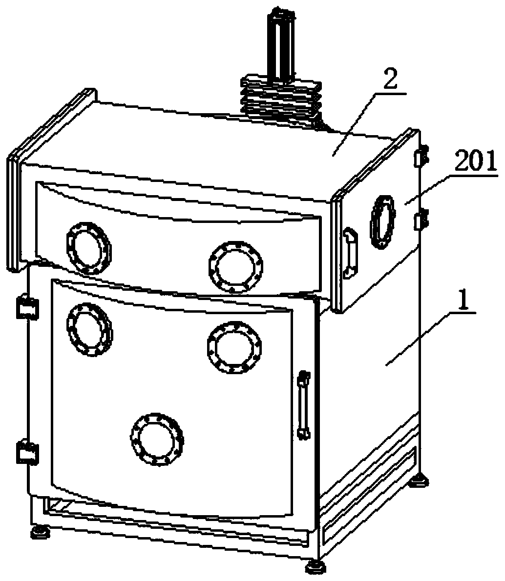
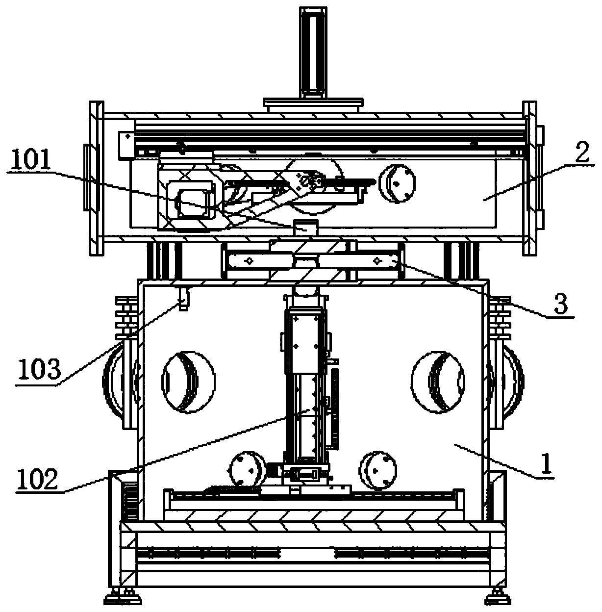
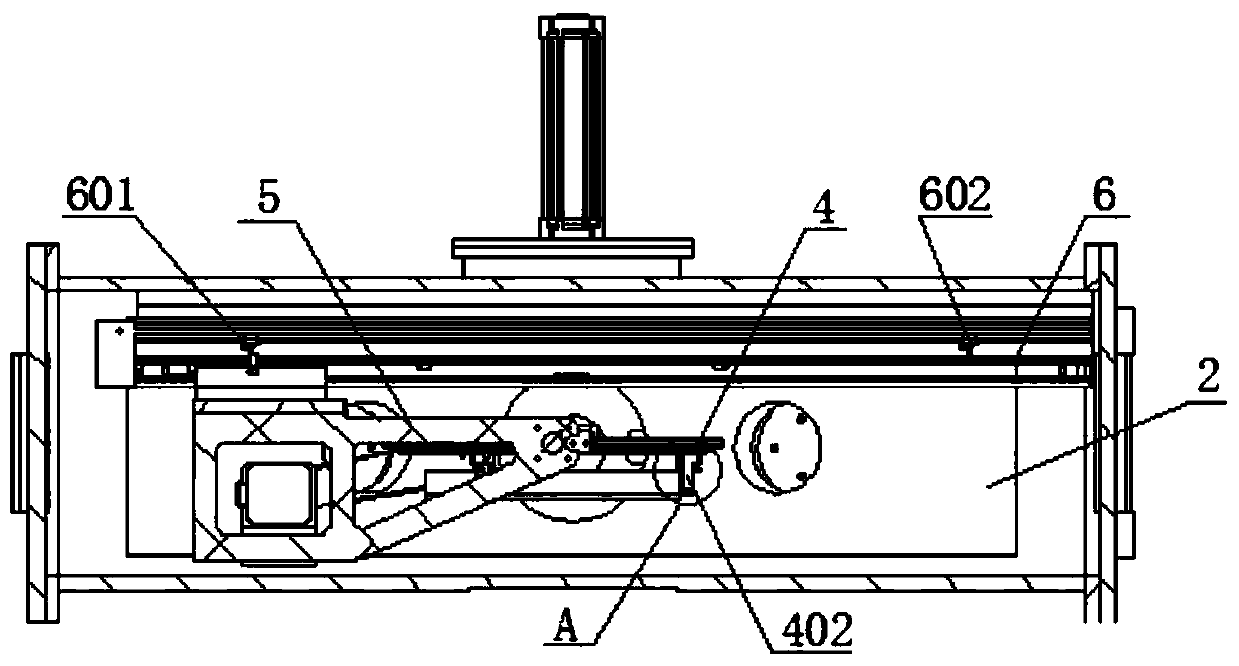
The invention provides a double-vacuum-chamber ion beam machining system and a machining method, and belongs to the technical field of ion beam machining. The ion beam machining system comprises an ion source vacuum chamber and a workpiece vacuum chamber which are communicated with each other, wherein the workpiece vacuum chamber is internally provided with a workpiece overturning and moving assembly which is hoisted in the workpiece vacuum chamber and used for fixing a workpiece to be machined and driving the workpiece to be machined to move and overturn in the workpiece vacuum chamber. The workpiece overturning and moving assembly comprises a workpiece chuck, a workpiece overturning vehicle and a linear module, wherein the workpiece overturning vehicle is connected with the workpiece chuck to drive the workpiece chuck to turn over; and the linear module is used for fixing the workpiece overturning vehicle so as to enable the workpiece overturning vehicle to move. According to the invention, a workpiece only needs to be fixed to the workpiece overturning and moving assembly of the workpiece vacuum chamber during feeding, the workpiece is driven by the workpiece overturning and moving assembly to move in the workpiece vacuum chamber, the workpiece does not need to be conveyed into the ion source vacuum chamber, and the feeding is easy; and the workpiece overturning and moving assembly drives the workpiece to overturn, the mounting and dismounting are convenient, the work efficiency is improved, and the work intensity is reduced.

Description

technical field [0001] The invention belongs to the technical field of ion beam processing, and specifically relates to a double vacuum chamber ion beam processing system. In addition, the invention also relates to a processing method for processing a workpiece by using the above double vacuum chamber ion beam processing system. Background technique [0002] The ion beam processing system is an ultra-precision processing equipment for high-precision processing of optical components. When the ion beam processing system is used for workpiece polishing, the interferometer is used to measure the surface shape of the part to be processed, and the surface error detection data is generated. To determine the process parameters and processing trajectory, polish the surface of the part to be processed under the control of the industrial computer, and control the residence time or moving speed of the ion beam on the surface of the part to accurately control the removal amount of the par...

Claims


Application Information

Patent Timeline
Patent Type & Authority Applications(China)
IPC IPC(8): H01J37/32
CPCH01J37/32431H01J37/32899
Inventor 宫文孙建坤
Owner 昆明凯航光电科技有限公司
Learn More