
Pressure welding device and pressure welding method

A technology of pressure head and pressing mechanism, which is applied in the direction of assembling printed circuits with electrical components, electrical components, and printed circuit manufacturing. It can solve problems such as damage to display panels and IC electrical components, and achieve safety hazards, uniform heating, and temperature rise. The effect of rate stabilization

Active Publication Date: 2020-06-02
BOE TECH GRP CO LTD +1
View PDF7 Cites 2 Cited by
  • Summary
  • Abstract
  • Description
  • Claims
  • Application Information

AI Technical Summary

Problems solved by technology

[0004] In view of the shortcomings of the existing methods, the present application proposes a pressure welding device and a pressure welding method to solve the technical problem in the prior art that the high temperature pressure head damages the display panel, IC, FPC and other electrical components

Method used


Image

  • Pressure welding device and pressure welding method
  • Pressure welding device and pressure welding method
  • Pressure welding device and pressure welding method

Examples


Embodiment Construction

[0028] The present application is described in detail below, and examples of embodiments of the present application are shown in the drawings, wherein the same or similar reference numerals denote the same or similar components or components having the same or similar functions throughout. Also, detailed descriptions of known technologies will be omitted if they are not necessary to illustrate the features of the present application. The embodiments described below by referring to the figures are exemplary only for explaining the present application, and are not construed as limiting the present application.

[0029] Those skilled in the art can understand that, unless otherwise defined, all terms (including technical terms and scientific terms) used herein have the same meanings as commonly understood by those of ordinary skill in the art to which this application belongs. It should also be understood that terms, such as those defined in commonly used dictionaries, should be ...


PUM


Abstract

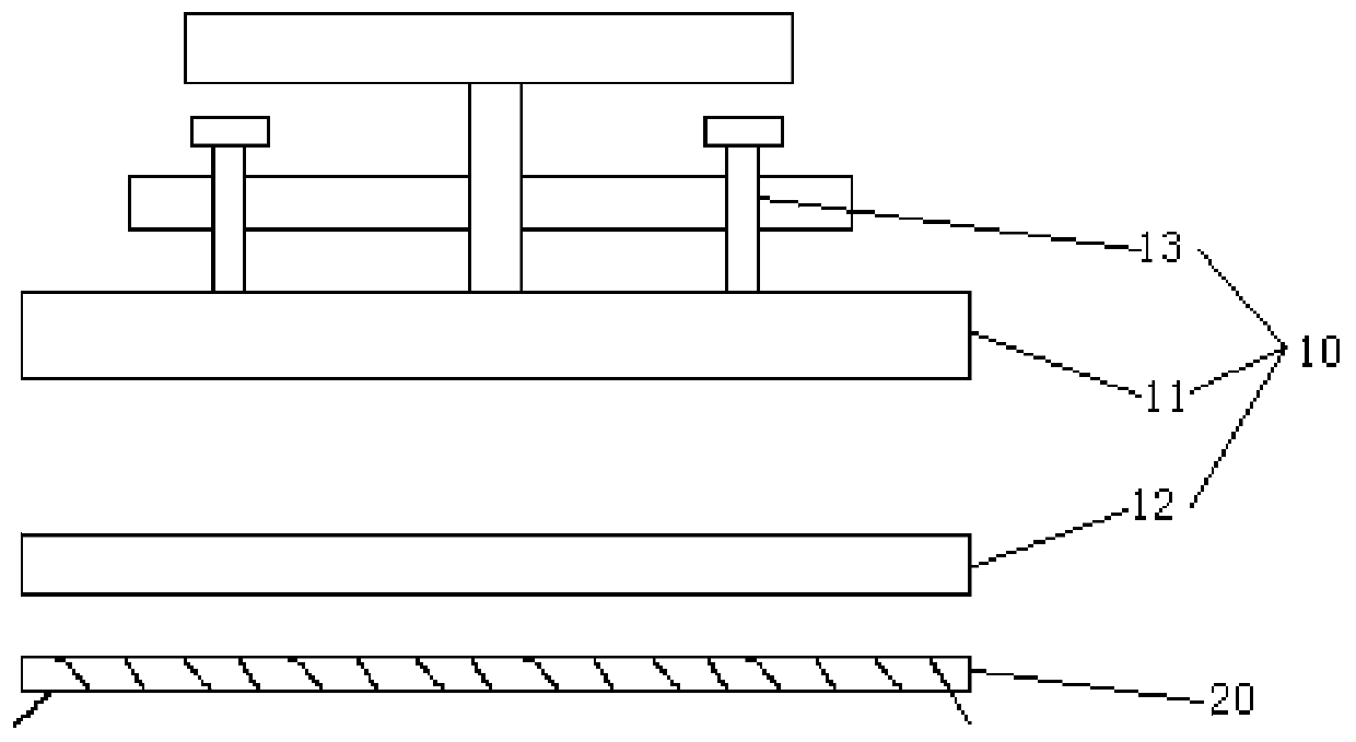
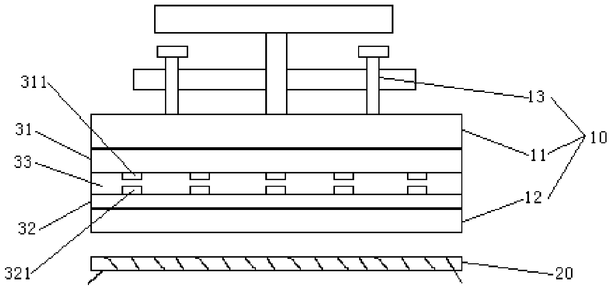
The embodiment of the invention provides a pressure welding device and a pressure welding method. The pressure welding device comprises a pressing mechanism and an induction heating mechanism, whereinthe pressing mechanism is used for pressing a display panel, an electrical component and a conductive adhesive film located between the display panel and the electrical component; and the induction heating mechanism is matched with the conductive adhesive film and used for generating an alternating magnetic field, so that the conductive adhesive film is self-heated and cured, and the display panel is fixedly connected with the electrical component. The alternating magnetic field is generated through the induction heating mechanism, so that a ferromagnetic material in the conductive adhesive film is enabled to generate heat to complete curing of an adhesive material in the conductive adhesive film. Compared with the prior art, through self-heating of the conductive adhesive film, the heating rate is more stable, the display panel and electrical components such as an IC and an FPC are heated more uniformly, and damage of a high-temperature pressure head to the display panel and the electrical components such as the IC and the FPC is avoided. Meanwhile, due to the fact that a hardware heat source is omitted, potential safety hazards brought by the high-temperature pressure head in the production process are avoided.

Description

technical field [0001] The invention relates to the technical field of display equipment processing, and in particular, the application relates to a pressure welding device and a pressure welding method. Background technique [0002] In the manufacturing process of display devices, most display panels need to connect electrical components such as driver chips (Integrated Circuit, referred to as IC) or flexible circuit boards (Flexible Printed Circuit, referred to as FPC) on their periphery. The connection and conduction of IC and FPC requires the use of conductive film, and the commonly used conductive film is Anisotropic Conductive Film (ACF for short). [0003] At present, under certain temperature and pressure conditions, the display panel is connected and conducted with electrical components such as IC and FPC through ACF. This pressure welding process is often called bonding (Bonding). In the existing process, high-temperature indenters are used to complete the pressur...

Claims


Application Information

Patent Timeline
Patent Type & Authority Applications(China)
IPC IPC(8): H05K3/30H05K3/36
CPCH05K3/305H05K3/365H05K2203/1105
Inventor 李明夏毓涵杨培梁承振邓皓丹李文刚郑伟唐敏
Owner BOE TECH GRP CO LTD
Learn More