Artifacts removal from tissue images

A technology for organizing images and artifacts, applied in the field of image analysis, can solve the problems of acquisition, expensive, time-consuming, etc., and achieve the effect of avoiding inconsistency and high accuracy

Pending Publication Date: 2020-06-02
F HOFFMANN LA ROCHE & CO AG
View PDF12 Cites 4 Cited by
  • Summary
  • Abstract
  • Description
  • Claims
  • Application Information

AI Technical Summary

Problems solved by technology

[0007] A problem associated with current denoising methods is that the generation of the noise removal logic involves a training phase of the machine learning logic on training data that is difficult to obtain in the required quantity and quality: often, images must be manually annotated for generation A training dataset where noise artifacts and / or tissue structures that look similar to the artifacts but should not be identified as noise artifacts are labeled as "true artifacts" or "real tissue structures"
The process is time consuming and requires hours, days or even weeks of work by one or more experienced pathologists
Furthermore, manual annotation of "true noise" and "real tissue" may be subjective, and different pathologists may have different insights into the nature of specific image parts that cannot be definitively classified as artifacts
Therefore, the creation of the artifact removal program logic currently requires the creation of the training dataset, which is very time consuming and thus expensive

Method used


Image

  • Artifacts removal from tissue images
  • Artifacts removal from tissue images
  • Artifacts removal from tissue images

Examples


Embodiment Construction

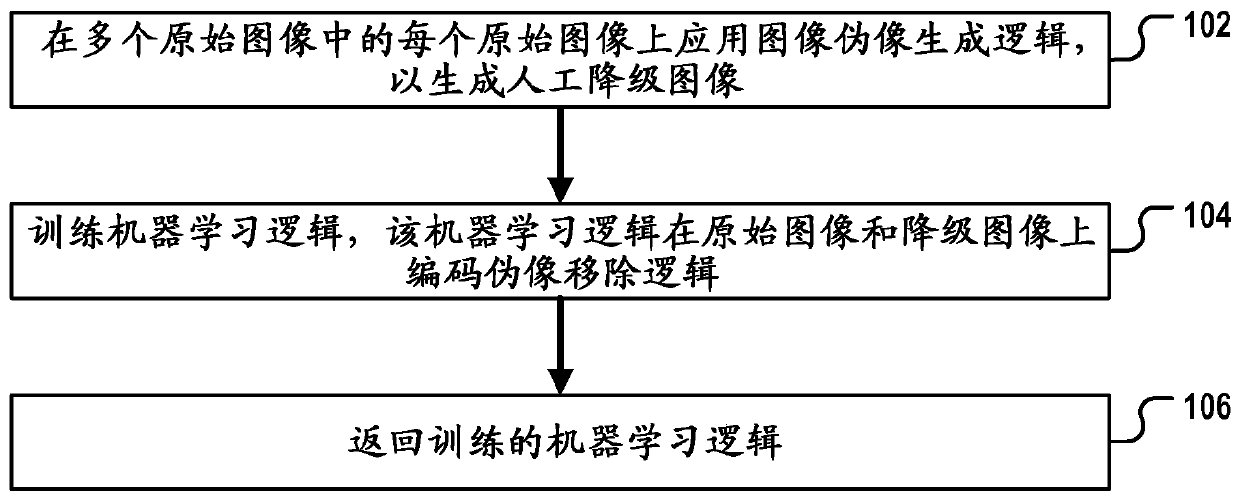
[0155] figure 1 is a flowchart of a method of generating artifact removal logic according to an exemplary embodiment of the present invention. The method can, for example, be based on figure 2 The image processing system of another embodiment of the present invention described in . In the following, reference will be made to figure 2 to describe figure 1 Methods.

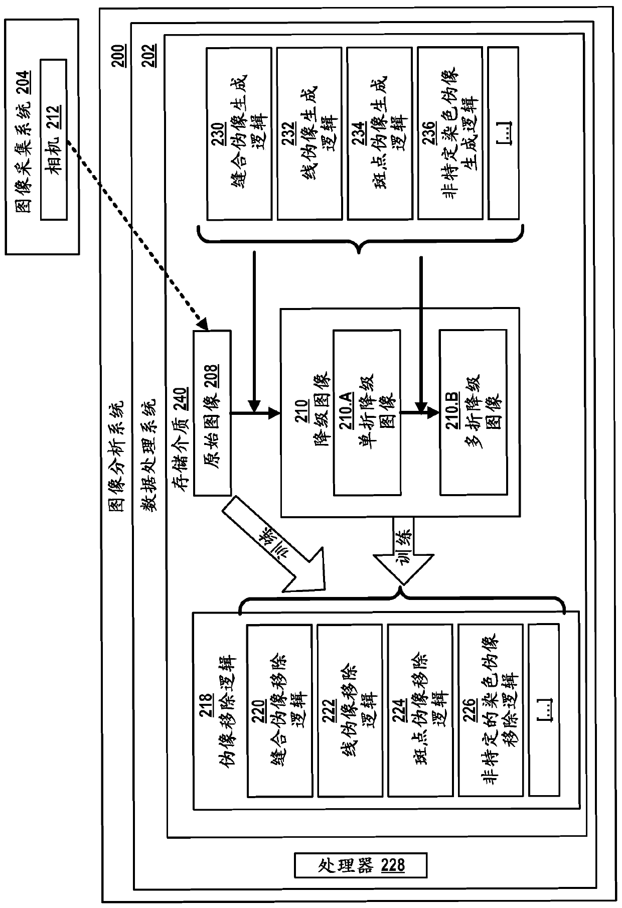
[0156] figure 2 An image analysis system 200 is shown. The system includes a data processing system 202 having one or more processors 228, such as a standard desktop computer system, notebook computer, tablet computer, or server computer system. The image analysis system 200 includes or is operably coupled to an image acquisition system 204, such as a brightfield or fluorescence microscope or a slide scanner. In the image acquisition system, a camera 212 is included. Data processing system 202 includes an interface for receiving digital images of tissue slides captured by camera 212 . For example, the ...


PUM


Abstract

The invention relates to a digital pathology method of generating program logic configured for removing artifacts from digital tissue images. The method comprises generating, for each of a plurality of original images, a first artificially degraded image by applying a first image-artifact-generation logic on each of the original images; and generating the program logic by training an untrained version of a first machine-learning logic that encodes a first artifacts-removal logic on the original images and their respectively generated first degraded images; and returning the trained first machine-learning logic as the program logic or as a component thereof. The first image-artifact-generation logic is A) an image-acquisition-system-specific image-artifact-generation logic or B) a tissue-staining-artifact-generation logic.

Description

technical field [0001] The present invention relates to image analysis, and more particularly to artifact removal in tissue images. Background technique [0002] In digital pathology, information encoded in digital images of tissue slides is extracted from the images to answer various biomedical questions, for example to assist healthcare professionals in the diagnosis and treatment of disease. The field of digital pathology is currently considered one of the most promising avenues in diagnostic medicine for better, faster and cheaper diagnosis, prognosis and prediction of cancer and other important diseases. Digital pathology technologies are also widely used in drug development settings to assist pathologists in understanding the microenvironment of tumors, how patients respond, how drugs work, and other information that can be obtained from tissue images. [0003] Scanned digital tissue images, especially at high magnifications, tend to have several types of noise associ...

Claims


Application Information

Patent Timeline
Patent Type & Authority Applications(China)
IPC IPC(8): G06T5/00
CPCG06N3/04G06T2207/10024G06T2207/10056G06T2207/20084G06T2207/20081G06T2207/30024G06T5/00G16H30/40G06N20/00G06T5/005
Inventor E·克莱曼
Owner F HOFFMANN LA ROCHE & CO AG
Why Eureka
Try Eureka