Cervical vertebra rehabilitation robot

A rehabilitation robot and cervical spine technology, applied in the field of cervical spine rehabilitation robot, can solve certain requirements, but also need other professionals to assist operation, impossible to move or carry, many nerves and muscles distribution and other problems, so as to achieve no risk of secondary injury , good adaptability, high intelligent effect

Pending Publication Date: 2020-06-05
阿米乐园智能科技(北京)有限公司
View PDF0 Cites 5 Cited by
  • Summary
  • Abstract
  • Description
  • Claims
  • Application Information

AI Technical Summary

Problems solved by technology

[0002] At present, there are usually two solutions for cervical spine rehabilitation training products. The first is a large-scale traction type with a fixed bed or a fixed chair, which requires the entire upper body and upper limbs to be fixed, which is costly, bulky, and complex in structure. Impossible to move or carry, there are certain requirements for the use environment, and other professionals are required to assist in the operation; the second is a portable product, which has a relatively simple structure, but does not have an active drive device, and relies on the principle of passive stretching to adjust the posture of the affected area. Adjustment and fixation to achieve rehabilitation effect
However, the distribution of joints, nerves, and muscles in the cervical spine is numerous and complex. For those who do not have professional knowledge in cervical spine rehabilitation, when adjusting and fixing the posture of the affected area, if the method is not scientific, the patient will be exacerbated directly, and there will be great risks and hidden dangers.

Method used


Image

  • Cervical vertebra rehabilitation robot
  • Cervical vertebra rehabilitation robot
  • Cervical vertebra rehabilitation robot

Examples


no. 1 example

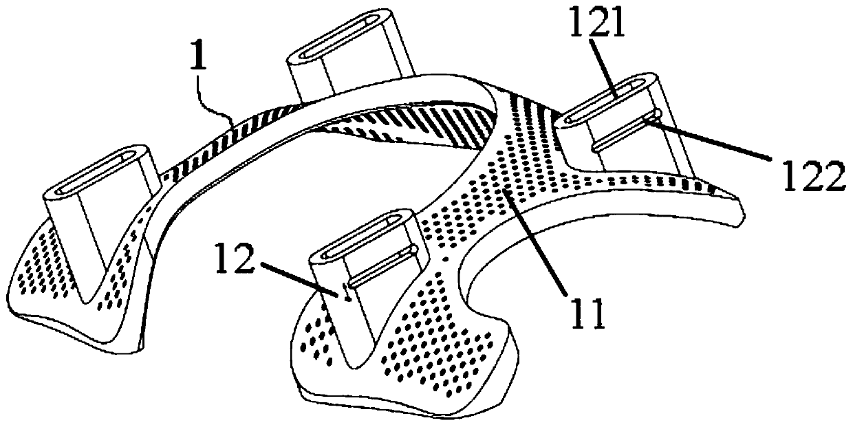
[0033] Please refer to Figure 1-Figure 7 , in the first embodiment of the present invention, the cervical spine rehabilitation robot includes: chest-back fixation support assembly 1;

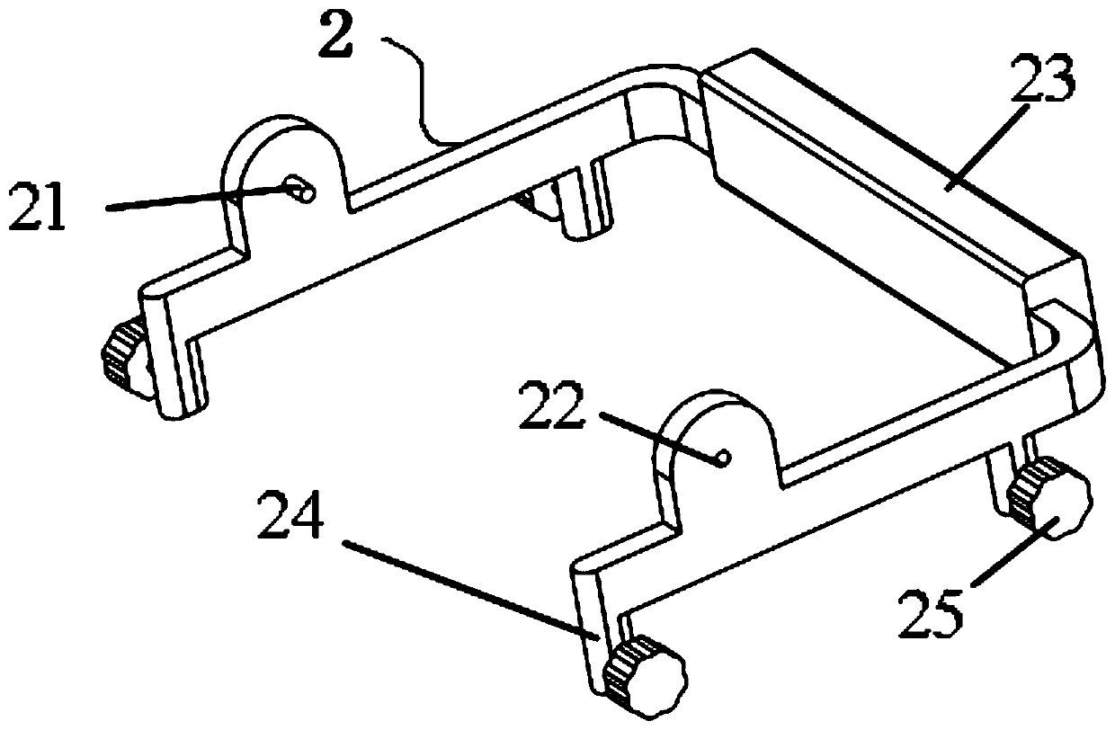
[0034] A chest-back support connection support frame 2, the chest-back support connection support frame 2 is installed on the top side of the chest-back support assembly 1;

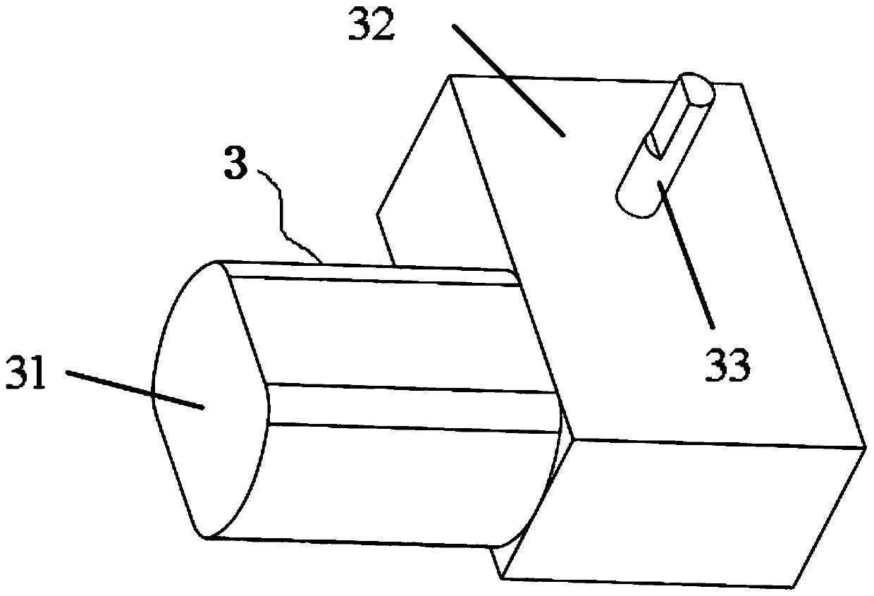
[0035] A reduction motor assembly 3, the reduction motor assembly 3 is installed on one side of the chest-back bracket connecting the support frame 2;

[0036] Neck adjustment fixed frame 4, described neck adjustment fixed frame 4 is installed between described chest-back supports connecting support frame 2;

[0037] Chin support bracket 5, said chin support bracket 5 is installed on the bottom of one side of said neck adjustment fixture 4;

[0038] Hindbrain support bracket 6, described hindbrain support bracket 6 is installed on the top side of described neck adjustment fixture 4.

[0039] The bottom of the chest and ...

no. 2 example

[0081] Based on the cervical spine rehabilitation robot provided in the first embodiment of the present application, the second embodiment of the present application proposes another cervical spine rehabilitation robot. The second embodiment is only a preferred mode of the first embodiment, and the implementation of the second embodiment will not affect the independent implementation of the first embodiment.

[0082] The second embodiment of the present invention will be further described below in conjunction with the drawings and implementation methods.

[0083] Please refer to Figure 8 The difference between this embodiment and the first embodiment is that two buffer clamping mechanisms 7 are symmetrically installed on the bottom side of the chest-back fixing support assembly 1, and the buffer clamping mechanisms 7 include a fixing column 71, and the bottom of the fixing column 71 The side slide is sleeved with a hemispherical chuck 72, and the fixed column 71 is sleeved wit...


PUM


Abstract

The invention provides a cervical vertebra rehabilitation robot. The cervical vertebra rehabilitation robot comprises a chest and back fixed support assembly; a chest and back support connection support frame installed on a top side of the chest and back fixed support assembly; a reduction motor assembly installed on one side of the chest and back support connection support frame; a neck adjustment fixing frame installed between the chest and back support connection support frame; a chin support frame installed at a bottom of one side of the neck adjustment fixing frame; and a back brain support frame installed on a top side of the neck adjustment fixing frame. The cervical vertebra rehabilitation robot has advantages of low cost, convenient carrying, strong adaptability, safety and reliability.

Description

technical field [0001] The invention relates to the technical field of rehabilitation equipment, in particular to a cervical spine rehabilitation robot. Background technique [0002] At present, there are usually two solutions for cervical spine rehabilitation training products. The first is a large-scale traction type, with a fixed bed or a fixed chair, which requires the entire upper body and upper limbs to be fixed, which is costly, bulky, and complex in structure. Impossible to move or carry, there are certain requirements for the use environment, and other professionals are required to assist in the operation; the second is a portable product, which has a relatively simple structure, but does not have an active drive device, and relies on the principle of passive stretching to adjust the posture of the affected area. Adjustment and fixation are carried out to achieve the rehabilitation effect. However, the distribution of joints, nerves, and muscles in the cervical spi...

Claims


Application Information

Patent Timeline
Patent Type & Authority Applications(China)
IPC IPC(8): A61H1/02
CPCA61H1/0296A61H2201/0157A61H2201/0173A61H2201/1207A61H2201/1609
Inventor 闫梁李辕吕世东
Owner 阿米乐园智能科技(北京)有限公司
Why Eureka
Try Eureka