Pulverized coal purging and separating device of medium-speed coal mill

A separation device, coal mill technology, applied in dryers, drying gas layout, grain processing and other directions, can solve the problems of large motor energy consumption, low work efficiency, affecting the safety and economy of the unit, etc., to make up for insufficient output, The effect of improving safety and economy

Pending Publication Date: 2020-06-05
北京必可测科技股份有限公司
View PDF0 Cites 0 Cited by
  • Summary
  • Abstract
  • Description
  • Claims
  • Application Information

AI Technical Summary

Problems solved by technology

[0004] During the grinding process, coal and coal powder are always mixed together, and there is a phenomenon that qualified coal powder is repeatedly ground, which consumes electric power in vain, and at the same time, the filling effect of fine powder affects the grinding effect of coarse coal.
At the same time, part of the qualified coal powder in the raw coal is scattered on the grinding table and moves outward to the hot air blowing place under the action of centrifugal force. Before being blown up by the hot air, there is no air flow to dry and remove the raw coal during the grinding process in this area. The pulverized coal with smaller particles and the pulverized coal that have been ground are transported away in time; therefore, repeated grinding of qualified fine powder consumes useless work, which eventually leads to insufficient output of the coal mill, low work efficiency, and high energy consumption of the motor; due to the current medium-speed In the actual operation of the coal mill, the coal quality deviates from the designed coal type, so most of them have the problem that the output cannot match the boiler load, resulting in no spare coal mill affecting the safety and economy of the unit

Method used


Image

  • Pulverized coal purging and separating device of medium-speed coal mill
  • Pulverized coal purging and separating device of medium-speed coal mill

Examples


Embodiment Construction

[0019] The following will clearly and completely describe the technical solutions in the embodiments of the present invention with reference to the accompanying drawings in the embodiments of the present invention. Obviously, the described embodiments are only some, not all, embodiments of the present invention. Based on the embodiments of the present invention, all other embodiments obtained by persons of ordinary skill in the art without making creative efforts belong to the protection scope of the present invention.

[0020] The object of the present invention is to provide a medium-speed coal pulverizer pulverized coal purging and separation device to solve the above-mentioned problems in the prior art and improve the safety and economy of the medium-speed coal pulverizer.

[0021] In order to make the above objects, features and advantages of the present invention more comprehensible, the present invention will be further described in detail below in conjunction with the a...


PUM


Abstract

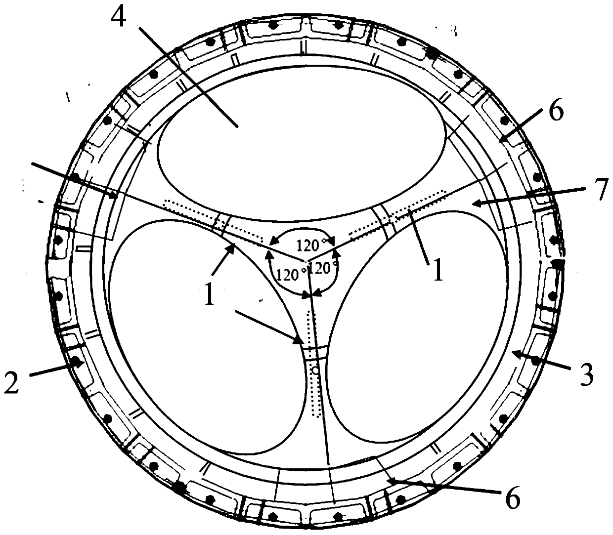
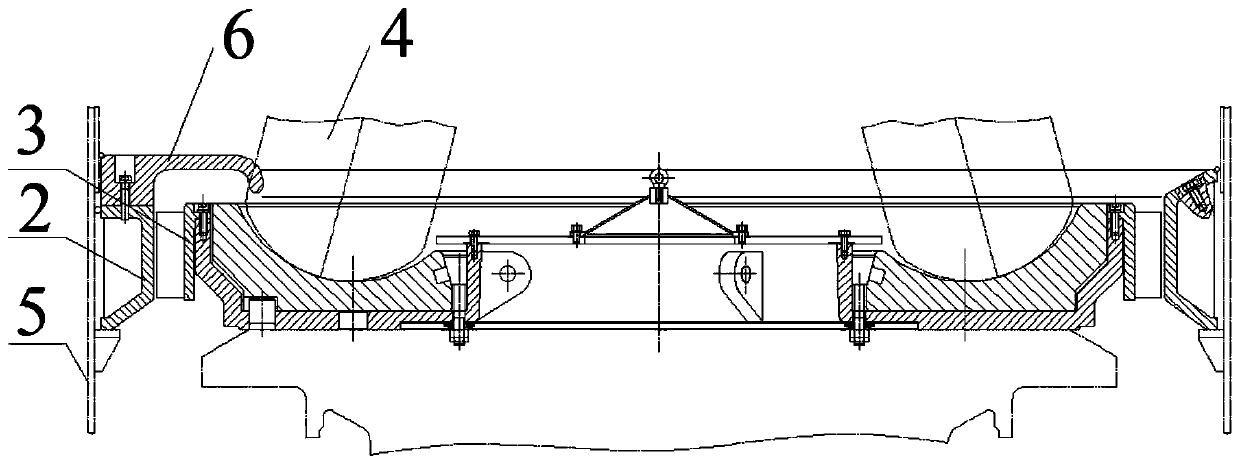
The invention discloses a pulverized coal purging and separating device of a medium-speed coal mill. The pulverized coal purging and separating device comprises a plurality of purging and separating units arranged between two adjacent milling rollers. At least one purging and separating unit is arranged between every two adjacent milling rollers. Each purging and separating unit comprises a pulverized coal stirrer and a static ring wind guide ring. The top end of each pulverized coal stirrer is fixedly connected with a separator outer powder cone of the medium-speed coal mill. One end of eachstatic ring wind guide ring is fixedly connected with the top of a static ring of the medium-speed coal mill. The other end of each static ring wind guide ring is provided with a downwards-inclining protruding part facing the mill rollers. A nozzle blade ring is fixedly arranged on a millstone tray of the medium-speed coal mill. The nozzle blade rings can rotate along with the rotation of a millstone. By means of the pulverized coal purging and separating device of the medium-speed coal mill, the safety and economic benefits of the medium-speed coal mill are improved.

Description

technical field [0001] The invention relates to the technical field of mining machinery, in particular to a pulverized coal purging and separating device for a medium-speed coal mill. Background technique [0002] ZGM coal mill is a medium-speed roller-disc coal mill. The grinding part is composed of a rotating grinding ring and three fixed and self-rotating grinding rollers rolling along the grinding ring. The raw coal to be ground falls onto the grinding ring from the central coal drop pipe of the mill, and the rotating grinding ring moves the raw coal to the grinding raceway by means of centrifugal force, where it is ground by the grinding rollers. The three grinding rollers are evenly distributed on the grinding disc raceway along the circumferential direction, and the grinding force is generated by the hydraulic loading system. Through the statically definite three-point system, the grinding force acts on the three grinding rollers evenly. , grinding roller, press fram...

Claims


Application Information

Patent Timeline
Patent Type & Authority Applications(China)
IPC IPC(8): B02C15/14B02C23/30F26B21/00
CPCB02C15/14B02C23/30B02C2015/002F26B21/004
Inventor 王斌何立荣
Owner 北京必可测科技股份有限公司
Why Eureka
Try Eureka