

SCR denitration device for controlling escape rate of ammonia, and working method thereof
A ammonia escape rate and denitrification technology, which is applied in the field of SCR denitrification devices to control ammonia escape rate, can solve the problems of reducing system economy and safety, affecting unit operation, and increasing labor intensity, so as to improve economy and safety, Prevent excessive ammonia from escaping, and the effect of scientific and reasonable device structure
- Summary
- Abstract
- Description
- Claims
- Application Information
AI Technical Summary
Problems solved by technology
Method used
Image

Examples
Embodiment Construction
[0016] The present invention will be further described in detail below in conjunction with the accompanying drawings and examples. The following examples are explanations of the present invention and the present invention is not limited to the following examples.
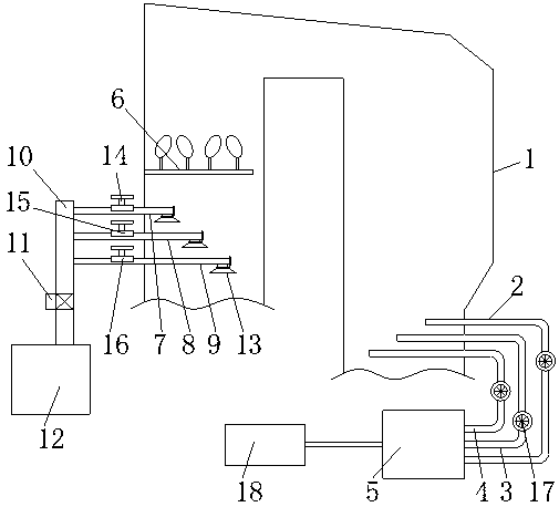
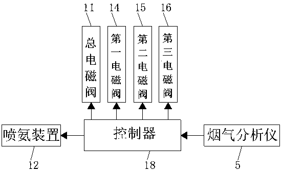
[0017] see Figure 1 to Figure 2 The SCR denitrification device for controlling the ammonia escape rate in this embodiment includes a denitrification system 1, one side of the denitrification system 1 is fixedly connected with a first pipeline 2, a second pipeline 3 and a third pipeline 4, the first pipeline 2, the second pipeline One end of the second pipeline 3 and the third pipeline 4 extends to the inside of the denitration system 1, and one end of the first pipeline 2, the second pipeline 3 and the third pipeline 4 are arranged sequentially from top to bottom inside the denitration system 1; Outside the system 1, the first pipeline 2, the second pipeline 3 and the third pipeline 4 are all fixedly connected with...
PUM
 Abstract
Description
Claims
Application Information