Motor stalling protection device and drive-by-wire hydraulic braking system

A protection device and motor stalling technology, applied in the field of vehicles, can solve problems such as linear hydraulic brake system failure, driving safety threats, motor high-temperature burnout, etc., to reduce the risk of high-temperature burnout, reduce viscosity, and increase reliability Effect

Active Publication Date: 2020-06-05
CHERY AUTOMOBILE CO LTD
View PDF6 Cites 3 Cited by
  • Summary
  • Abstract
  • Description
  • Claims
  • Application Information

AI Technical Summary

Problems solved by technology

[0005] When the braking intensity is high, the motor often needs to work in a locked-rotor condition (that is, the output shaft of the motor cannot rotate). Being in a locked-rotor condition for

Method used


Image

  • Motor stalling protection device and drive-by-wire hydraulic braking system
  • Motor stalling protection device and drive-by-wire hydraulic braking system
  • Motor stalling protection device and drive-by-wire hydraulic braking system

Examples


Embodiment Construction

[0040] In order to make the purpose, technical solution and advantages of the present application clearer, the implementation manners of the present application will be further described in detail below in conjunction with the accompanying drawings.

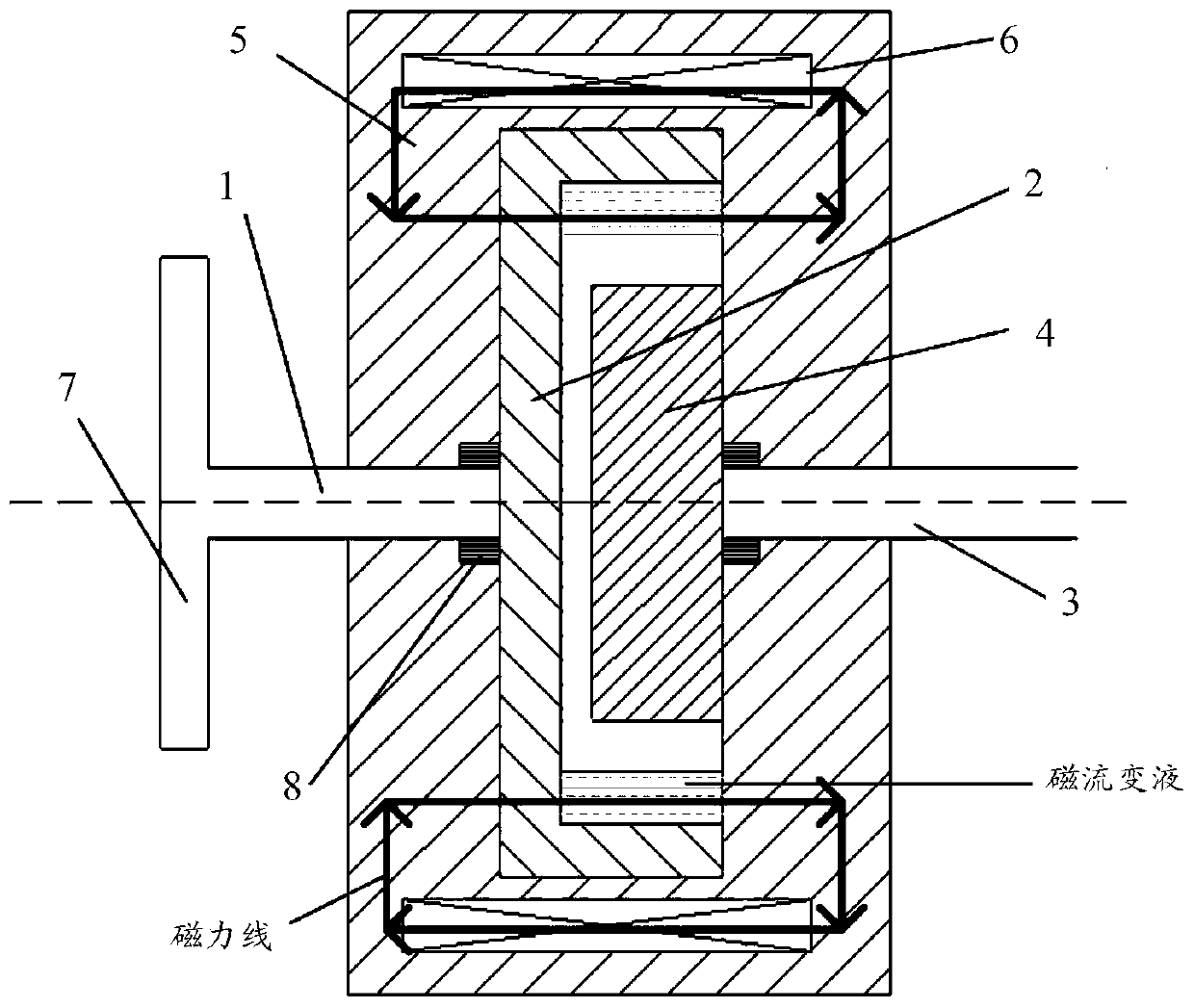
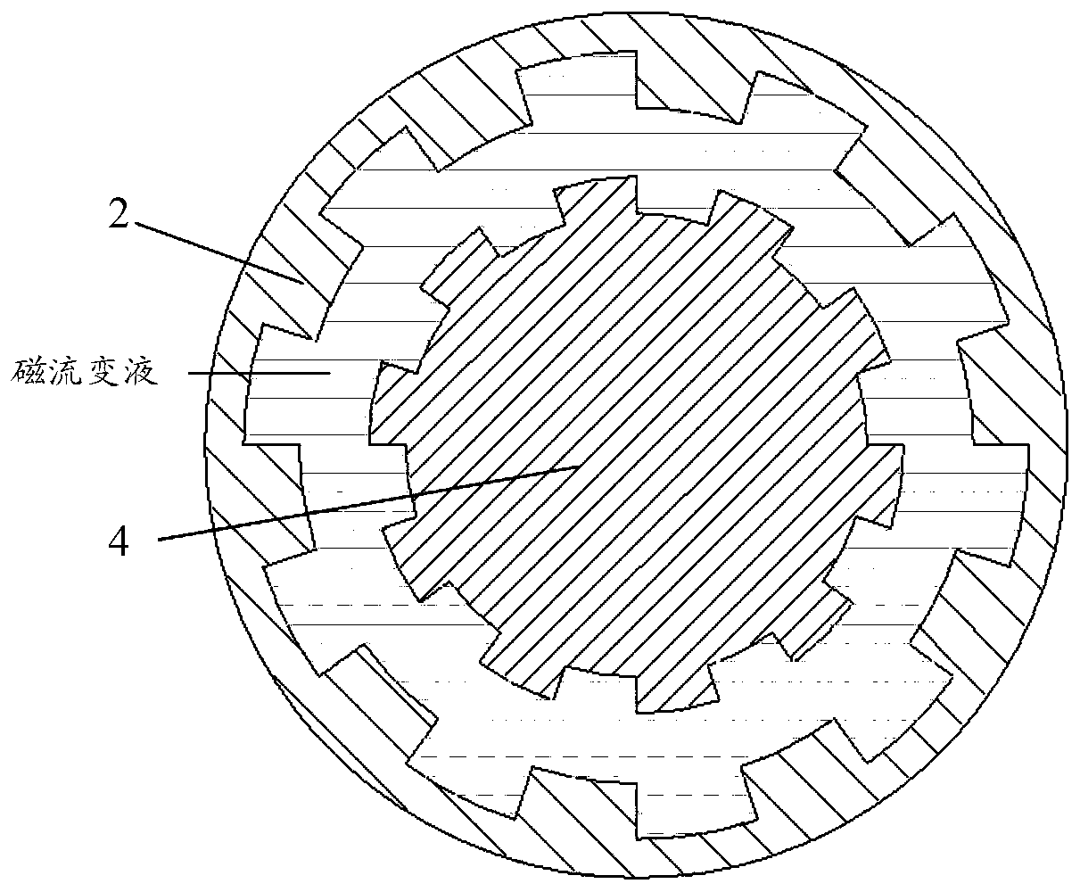
[0041] The embodiment of the present application provides a motor stall protection device, such as figure 1 and figure 2 As shown, the motor stall protection device includes an input shaft 1, a driving disc 2, an output shaft 3, a driven disc 4, a housing 5 and an excitation coil 6, wherein the input shaft 1 is fixedly connected to the driving disc 2, and the output shaft 3 is connected to the The driven disk 4 is fixedly connected. The input shaft 1 and the output shaft 3 pass through the housing 5 , the driving disc 2 and the driven disc 4 are arranged inside the housing 5 , and the driving disc 2 and the driven disc 4 are not in contact. A cavity is formed among the casing 5 , the driving disc 2 and the driven disc 4 , and ...


PUM


Abstract

The invention relates to a motor stalling protection device and a drive-by-wire hydraulic braking system comprising the motor stalling protection device, and belongs to the technical field of vehicles. The motor stalling protection device comprises an input shaft, a driving disc, an output shaft, a driven disc, a shell and a magnet exciting coil, the input shaft is fixedly connected with the driving disc, and the output shaft is fixedly connected with the driven disc; the input shaft and the output shaft penetrate through the shell, the driving disc and the driven disc are arranged in the shell, and the driving disc does not make contact with the driven disc. A cavity is formed among the shell, the driving disc and the driven disc, and magnetorheological fluid is arranged in the cavity; and the magnet exciting coil is arranged in the shell. By the adoption of the method, the risk of high-temperature burnout of the motor can be effectively reduced, and the reliability of the drive-by-wire hydraulic braking system is improved.

Description

technical field [0001] The present application relates to the technical field of vehicles, in particular to a motor stall protection device and a wire-controlled hydraulic braking system. Background technique [0002] The automobile brake system is an extremely important system to ensure the safety of automobile driving. As one of the most popular research directions at present, the wire-controlled hydraulic brake system Dynamic anti-lock braking and other functions. [0003] There is a control-by-wire hydraulic brake system in the related art, which includes three parts: a pedal assembly, an electronic control unit and a brake actuator. Among them, the motor output displacement and torque are mostly used in the brake actuator, and the rotational motion of the motor is converted into linear motion through the brake reducer and brake, and then the braking resistance torque is output. [0004] During the process of implementing this application, the applicant found that ther...

Claims


Application Information

Patent Timeline
IPC IPC(8): B60T13/74B60T7/06B60T17/22
CPCB60T7/06B60T13/74B60T17/22
Inventor 韦圣兵俞兆伟赛影辉储亚峰瞿元杨梅
Owner CHERY AUTOMOBILE CO LTD
Why Eureka
Try Eureka