A hardware storage box for computer interaction

A storage box and computer technology, applied in the computer field, can solve the problems of poor use effect, falling to the ground, difficult to take, etc., and achieve the effect of improving the use effect, easy to take, and convenient to access hard disks

Active Publication Date: 2021-01-29
光禹莱特数字科技(上海)有限公司
View PDF14 Cites 0 Cited by
  • Summary
  • Abstract
  • Description
  • Claims
  • Application Information

AI Technical Summary

Problems solved by technology

[0003] At present, when storing a large number of hard disks, storage boxes are usually used for storage. However, the existing storage boxes still have certain deficiencies. During use, some hard disks in the storage boxes are directly placed in the box. When taking it, it is easy to fall to the ground due to the shaking of the box and cause damage. Some hard disks in the storage box are stuck in the box. Therefore, there is an urgent need to design a hardware storage box for computer interaction to solve the above problems

Method used


Image

  • A hardware storage box for computer interaction
  • A hardware storage box for computer interaction
  • A hardware storage box for computer interaction

Examples


Embodiment 1

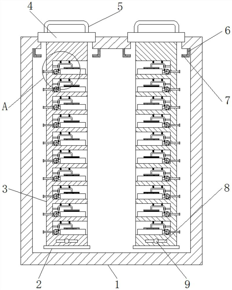
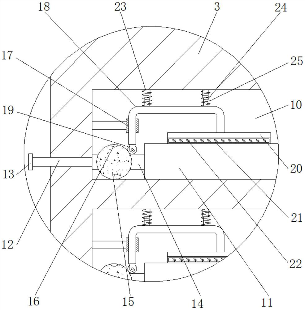
[0027] refer to Figure 1-4 , a hardware storage box for computer interaction, comprising a box body 1, the top outer wall of the box body 1 is provided with installation ports equidistant and annularly distributed, and the inner wall of the installation port is inserted with a storage tube 3, and the top outer wall of the storage tube 3 The top plate 4 is welded, and the top outer wall of the top plate 4 is fixedly connected with the handle 5, and the outer wall of one side of the storage tube 3 is provided with storage slots 10 distributed equidistantly, and the hard disk body 11 is placed inside the storage slot 10, and the storage slot 10 The inner wall of one side of the side rod is welded with a side bar, and the outer wall of one end of the side bar is welded with a limit tube 17, and the inner wall of the limit tube 17 is slidably connected with a connecting rod 18, and the shape of the connecting rod 18 is U-shaped, and the bottom outer wall of the connecting rod 18 A...

Embodiment 2

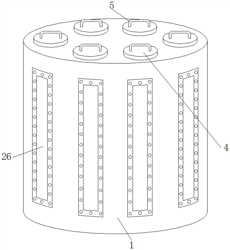
[0031] refer to Figure 5 , a hardware storage box for computer interaction. Compared with Embodiment 1, this embodiment also includes a fixing hole on the top outer wall of the box body 1, and a dehumidification cylinder 27 is inserted into the inner wall of the fixing hole, and the outer wall of the dehumidification cylinder 27 A mounting plate 30 is welded, a plug 31 is plugged into the inner wall of the dehumidification cylinder 27, a drying ball 29 is placed inside the dehumidification cylinder 27, and the outer wall of the dehumidification cylinder 27 has multiple rows of air holes 28 equidistant and circularly distributed.

[0032] Working principle: When in use, the moist water in the cabinet 1 can enter the dehumidification cylinder 27 through the vent hole 28 and be absorbed by the drying ball 29, so that the cabinet 1 can maintain a dry storage environment for a long time, and it is easy to pass through the installation plate 30 The dehumidification cylinder 27 is p...


PUM


Abstract

The invention discloses a hardware storage box for computer interaction. The top outer wall of the top plate is provided with a top plate, and the top outer wall of the top plate is fixedly connected with a handle, and one side of the outer wall of the storage tube is provided with storage slots distributed equidistantly, and a hard disk body is placed inside the storage slot, and the storage slot A side rod is welded on the inner wall of one side, and a limiting cylinder is arranged on the outer wall of one end of the side rod, the inner wall of the limiting cylinder is slidably connected with a connecting rod, and the shape of the connecting rod is U-shaped, and the bottom outer wall of the connecting rod is provided with The backing plate is welded with a sleeve on the top inner wall of the receiving groove. The invention makes the hard disk body easy to take and avoid damage caused by falling to the ground due to the shaking of the box body. The use effect is better, and the hard disk is more convenient to access, which further improves the use effect of the device.

Description

technical field [0001] The invention relates to the technical field of computers, in particular to a hardware storage box for computer interaction. Background technique [0002] Computer interactive hardware is an essential part of people's use of computers. It is a medium for communication and information exchange between people and computers. Among them, hard disk is an important tool that people need to use for storage, especially for companies that need to do a lot of storage work. For departments and departments, the storage and storage of hard disks is very important. [0003] At present, when storing a large number of hard disks, storage boxes are usually used for storage. However, the existing storage boxes still have certain deficiencies. During use, some hard disks in the storage boxes are directly placed in the box. When taking it, it is easy to fall to the ground due to the shaking of the box and cause damage. Some hard disks in the storage box are stuck in the ...

Claims


Application Information

Patent Timeline
Patent Type & Authority Patents(China)
IPC IPC(8): B65D25/02B65D25/10B65D25/20B65D25/28B65D25/38B65D81/05B65D81/26
CPCB65D25/02B65D25/101B65D25/20B65D25/282B65D25/38B65D81/05B65D81/266
Inventor 李兴文
Owner 光禹莱特数字科技(上海)有限公司
Why Eureka
Try Eureka