
Sliding plate control device for converter sliding plate slag blocking

A sliding plate slag blocking and control device technology, applied in the direction of manufacturing converters, etc., can solve the problems of reducing the life of the sliding plate, prone to cracks, collision impact, etc., and achieve the effect of improving the service life, avoiding cracks, and enhancing stability.

Inactive Publication Date: 2020-06-05
ANHUI YUNTIAN METALLURGY TECH
View PDF9 Cites 5 Cited by
  • Summary
  • Abstract
  • Description
  • Claims
  • Application Information

AI Technical Summary

Problems solved by technology

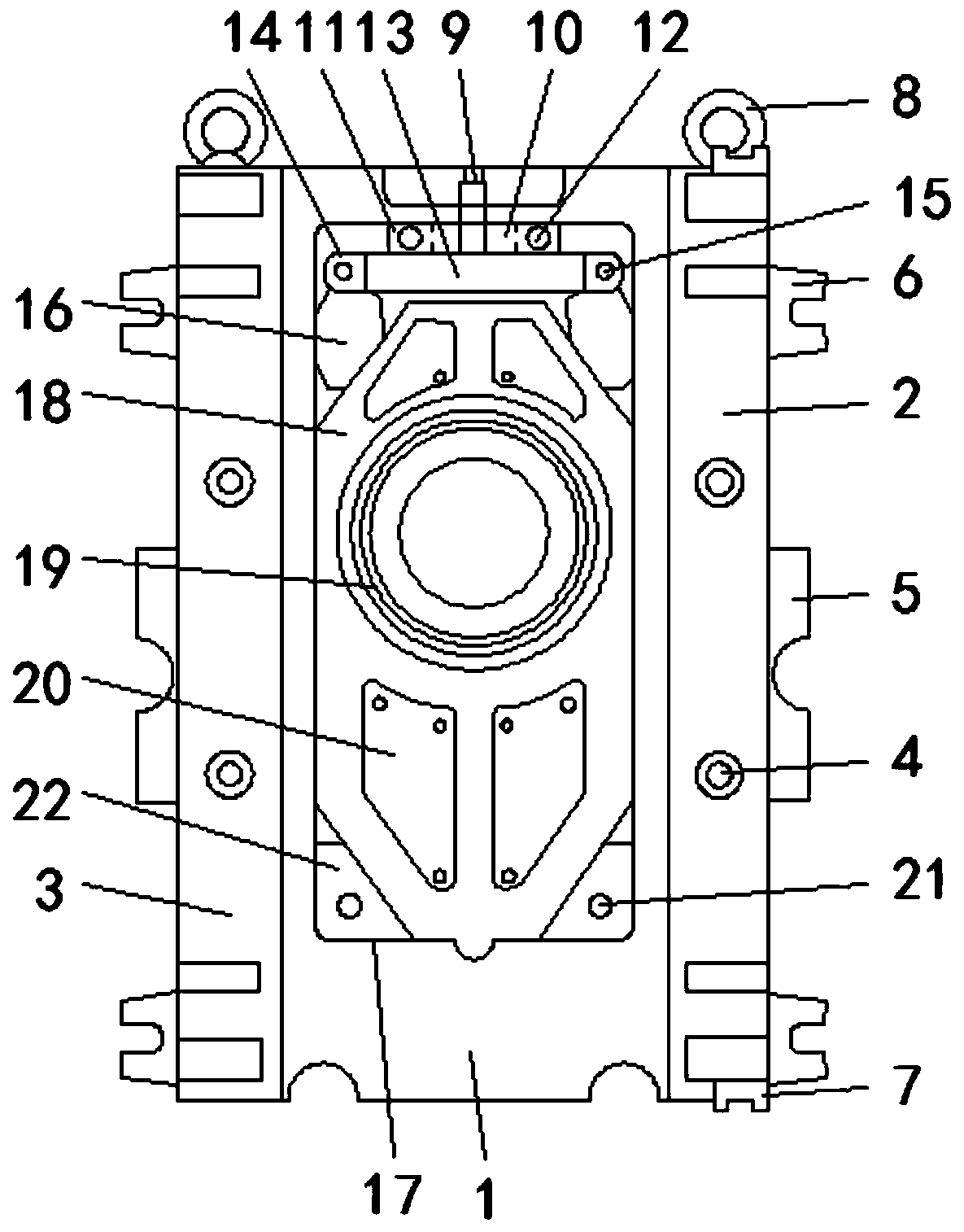
[0005] Aiming at the deficiencies of the prior art, the present invention provides a sliding plate control device for converter sliding plate slag blocking, which has the advantage of effectively avoiding the cracks of the sliding plate due to impact, and solves the problem that the upper and lower sliding plates will move relative to each other when the oil cylinder pulls the sliding plate at high speed. That is, when the skateboard moves and collides with the mold frame, the skateboard is a high-hardness product, so it is prone to cracks, reducing the life of the skateboard or causing steel accidents

Method used


Image

  • Sliding plate control device for converter sliding plate slag blocking
  • Sliding plate control device for converter sliding plate slag blocking

Examples


Embodiment Construction

[0023] The following will clearly and completely describe the technical solutions in the embodiments of the present invention with reference to the accompanying drawings in the embodiments of the present invention. Obviously, the described embodiments are only some, not all, embodiments of the present invention. Based on the embodiments of the present invention, all other embodiments obtained by persons of ordinary skill in the art without making creative efforts belong to the protection scope of the present invention.

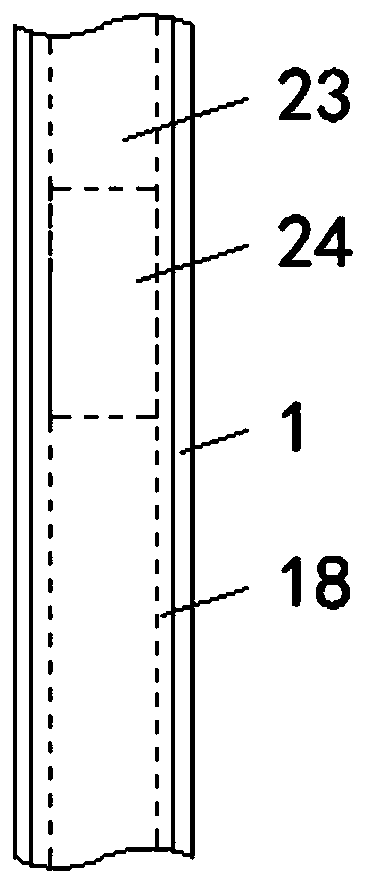
[0024] see Figure 1-2 , a sliding plate control device for converter sliding plate slag blocking, comprising a mold frame 1, the top of the mold frame 1 is equidistantly provided with fixing holes, the right end of the front of the mold frame 1 is fixedly connected with a right fixing plate 2, and the left end of the front of the mold frame 1 is fixed The left fixed plate 3 is connected, the areas of the right fixed plate 2 and the left fixed plate 3 are equa...


PUM


Abstract

The invention relates to the technical field of converters, and discloses a sliding plate control device for converter sliding plate slag blocking. The sliding plate control device for converter sliding plate slag blocking comprises a mold frame, a right fixing plate is fixedly connected to the right end of the front of the mold frame, and a left fixing plate is fixedly connected to the left end of the front of the mold frame; and the front of the right fixing plate and the front of the left fixing plate are connected with fixing screws in a threaded mode, the middle parts of the left side andthe right side of the mold frame are fixedly connected with limiting blocks, the top ends and the bottom ends of the left side and the right side of the mold frame are fixedly connected with chucks,and positioning blocks are fixedly connected to the top and bottom of the right fixing plate. According to the sliding plate control device for converter sliding plate slag blocking, after a sliding plate is installed in the mold frame, and an adjusting screw is rotated to push a push plate to move downwards, so that a power arm moves inside a movable groove; two symmetrically arranged movable blocks hold the sliding plate tightly, so that the sliding plate is fixed in the mold frame; and the impact force of the sliding plate and a cushion block is used, cracks caused by the impact of the sliding plate are effectively avoided, and the service life of the sliding plate is prolonged.

Description

technical field [0001] The invention relates to the technical field of converters, in particular to a sliding plate control device for a converter sliding plate slag blocking. Background technique [0002] The converter body is rotatable and is used for metallurgical furnaces for blowing steel or blowing matte. The converter body is made of steel plate, in a cylindrical shape, and lined with refractory materials. It is heated by chemical reaction heat during blowing, and no external heating source is required. , is the most important steelmaking equipment, and can also be used for copper and nickel smelting. According to the refractory properties of the furnace lining, the converter is divided into alkaline (with magnesia or dolomite as the lining) and acidic (with siliceous material as the lining) Converters are divided into bottom blowing, top blowing and side blowing converters according to the part where the gas is blown into the furnace. According to the gas used in blo...

Claims


Application Information

Patent Timeline
Patent Type & Authority Applications(China)
IPC IPC(8): C21C5/46
CPCC21C5/4653
Inventor 金福梅
Owner ANHUI YUNTIAN METALLURGY TECH
Learn More