Blasting structure and blasting method

A technology of cutting holes at the bottom, which is applied in the field of coal mine blasting, can solve the problem that the blasting footage cannot meet the construction requirements, and achieve the effect of good safety

Pending Publication Date: 2020-06-05
HUAINAN MINING IND GRP
View PDF0 Cites 2 Cited by
  • Summary
  • Abstract
  • Description
  • Claims
  • Application Information

AI Technical Summary

Problems solved by technology

[0003] The technical problem to be solved by the present invention is: the technical problem that the blasting footage in the prior art cannot meet the construction requirements

Method used


Image

  • Blasting structure and blasting method
  • Blasting structure and blasting method
  • Blasting structure and blasting method

Examples


Embodiment 1

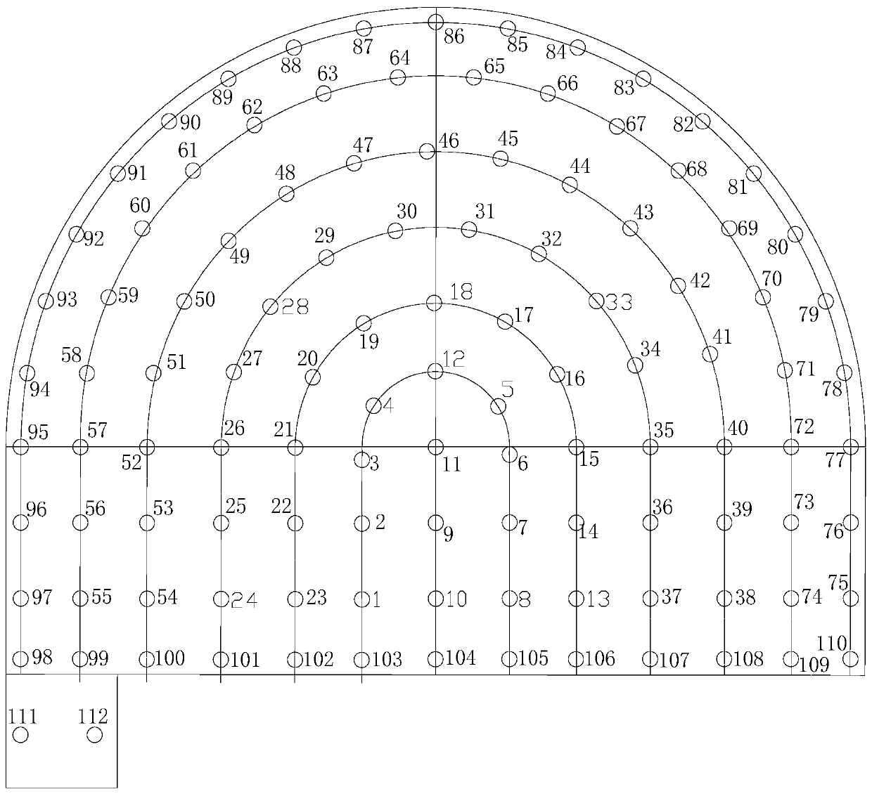
[0046] like figure 1 As shown, a blasting structure includes an auxiliary cut hole, a cut hole, a second ring hole, a third ring hole, a fourth ring hole, a fifth ring hole, a peripheral hole, a bottom hole, and a gutter hole.

[0047] like figure 1 As shown, the auxiliary cutouts are set in the middle of the blasting section, and the auxiliary cutouts are distributed at intervals up and down, and the distance between adjacent auxiliary cutouts is 480-520mm; in this embodiment, four auxiliary cutouts are set, namely figure 1 For blastholes marked as 9, 10, 11, and 12, the distance between adjacent auxiliary cutting holes is 500mm.

[0048] like figure 1 As shown, the cut eye ( figure 1 The blastholes marked as 1-8), the second ring holes ( figure 1 The blast hole marked as 13-23), the peripheral eye ( figure 1 The blastholes with the marks 75-97) are opened in the periphery of the auxiliary cutout hole in turn, and the cutout hole, the second ring hole, and the peripheral...

Embodiment 2

[0069] A blasting method based on the aforementioned blasting structure, comprising the steps of:

[0070] S1. Select blasting section;

[0071] S2. Drilling: Drilling holes on the blasting section according to the size in Embodiment 1;

[0072] S3, charging:

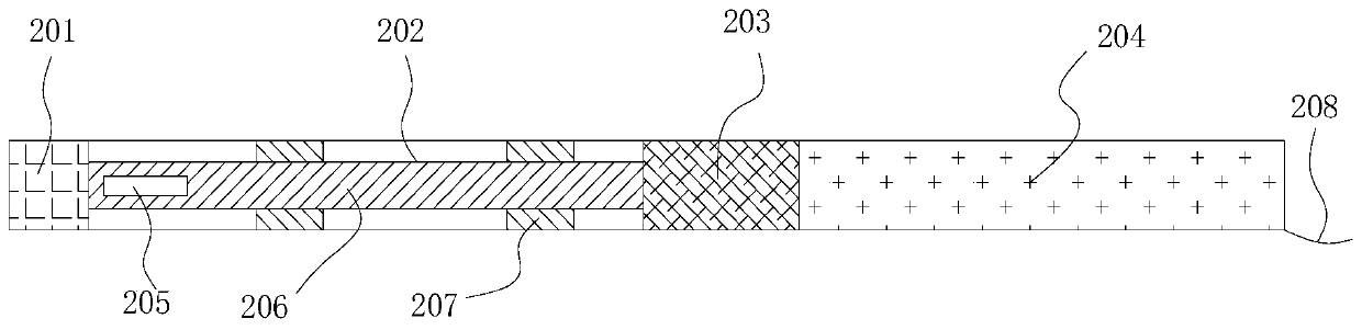
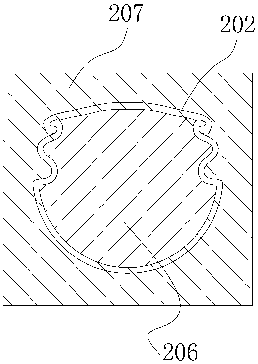
[0073]Peripheral eye charging: put the detonator roll containing the detonator 205 and the explosive 206 into the energy-concentrating tube 202, specifically place the detonator roll containing the detonator 205 and the explosive 206 in the energy-concentrating tube 202, and cover the cover sheet, then Bind the two ends of the energy-gathering tube 202 firmly with adhesive tape to ensure that the medicine rolls are tightly connected, put the seat mud 201 into the fundus of the peripheral eye, and then install the energy-gathering tube 202 in the peripheral eye through the positioning block 207, except for the most The detonators 205 in the peripheral eyes of the lower two rows of eyes are located at the end close to t...


PUM


Abstract

The invention discloses a blasting structure and a blasting method. The blasting structure comprises auxiliary cutholes, cutholes, two circles of holes and peripheral holes; the auxiliary cutholes areformed in the middle of the blasting section, the auxiliary cutholes are distributed up and down at intervals, and the distance between every two adjacent auxiliary cutholes is 480-520 mm; the cutholes, the two circles of holes and the peripheral holes are sequentially formed in the peripheries of the auxiliary cutholes and distributed in the corresponding virtual inverted U-shaped lines correspondingly, the distance between the straight line position of each U-shaped line of each cuthole and the vertical line where the corresponding auxiliary cuthole is located is 480-520 mm; the distance between the U-shaped line of the two circle of holes and the U-shaped line of the cuthole is 450-500 mm, and if no other holes are formed between the two circle of holes and the peripheral holes, the distance between the U-shaped line of the peripheral holes and the U-shaped line of the two circle of holes is 400-500 mm; and the method comprises the following steps of selecting a blasting section, drilling, charging and blasting. The method has the advantages that the requirement for footage during actual blasting can be met, and the requirement for rapid tunneling can be met.

Description

technical field [0001] The invention relates to the field of coal mine blasting, in particular to a blasting structure and a blasting method. Background technique [0002] The smooth surface blasting of the energy-concentrating tube is based on the principle of energy-concentrating blasting (using the linear energy-concentrating charge cover to gather explosive energy to conduct directional cutting on the engineering target, so as not to damage the surrounding rock around the roadway to be protected, and to improve the energy utilization rate of the explosive), Explosion products produce energy-gathering effect on the linear liner, and the potential energy of the explosion product is converted into jet kinetic energy through the symmetrical liner, cutting cracks on the rock. Under the action of high-pressure blasting gas quasi-stress and gas blade, according to The phenomenon of stress concentration is broken in the direction of the centerline of the energy gathering angle, ...

Claims


Application Information

Patent Timeline
Patent Type & Authority Applications(China)
IPC IPC(8): F42D1/00F42D3/04
CPCF42D1/00F42D3/04
Inventor 马祥银杨选刚刘运启杨维孔杨少东朱永东
Owner HUAINAN MINING IND GRP
Why Eureka
Try Eureka