Space three-dimensional coordinate measuring instrument system and three-dimensional control network measuring method thereof

A three-dimensional coordinate and three-dimensional control technology, applied in measuring instruments, measuring devices, active optical measuring devices, etc., can solve problems such as uneven distribution, inability to achieve accurate transmission of control network point coordinates, and inability to realize coordinate transmission, and achieve accurate transmission. Effect

Active Publication Date: 2020-06-05
PLA STRATEGIC SUPPORT FORCE INFORMATION ENG UNIV PLA SSF IEU
View PDF4 Cites 9 Cited by
  • Summary
  • Abstract
  • Description
  • Claims
  • Application Information

AI Technical Summary

Problems solved by technology

[0006] The purpose of the present invention is to provide a space three-dimensional coordinate measuring instrument system, which is used to solve the problem that the existing three-dimensional coordinate measuring instrument system cannot realize the accurate transfer of control network point coordinates when the visibility conditions are

Method used


Image

  • Space three-dimensional coordinate measuring instrument system and three-dimensional control network measuring method thereof
  • Space three-dimensional coordinate measuring instrument system and three-dimensional control network measuring method thereof
  • Space three-dimensional coordinate measuring instrument system and three-dimensional control network measuring method thereof

Examples


Embodiment Construction

[0039] The specific embodiments of the present invention will be further described below in conjunction with the drawings.

[0040] System embodiment:

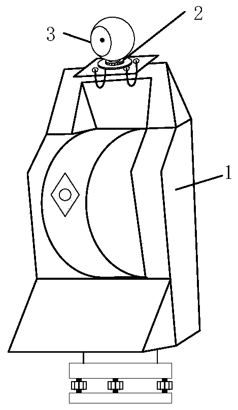
[0041] A three-dimensional coordinate measuring instrument system of this embodiment includes two modified laser trackers and two spherical prisms. The combined effect of the modified laser tracker and the spherical prism is as follows figure 1 As shown, the spherical prism target base 2 is installed on the top of the laser tracker. The spherical prism target base 2 is used to place the spherical prism 3 so that the center of the spherical prism 3 is on the vertical axis of the laser tracker 1. Among them, the structure of the spherical prism 3 is image 3 As shown, the structure of the spherical prism target base 2 is Figure 8 As shown, the spherical prism target base is a cylindrical sleeve with a boss at the bottom, and the cylindrical sleeve is tangent to the spherical prism to be assembled, so that the center of the spherical ...


PUM


Abstract

The invention relates to a space three-dimensional coordinate measuring instrument system and a three-dimensional control network measuring method thereof, and belongs to the field of precision industry and engineering measurement. The system comprises two three-dimensional coordinate measuring instruments, a spherical prism is fixed at the top of each three-dimensional coordinate measuring instrument; when the two three-dimensional coordinate measuring instruments are used for measuring the three-dimensional control network, the two three-dimensional coordinate measuring instruments are controlled to mutually aim at and measure the spherical prism at the top of the three-dimensional coordinate measuring instruments so as to obtain a mutual aiming observation value between the three-dimensional coordinate measuring instruments, establish a parameter balancing model according to the mutual aiming observation value in combination with the observation value of each control network point in the three-dimensional control network, and carry out solving to obtain the coordinate of the control point under the condition of taking a certain observation station as a reference observation station and the translation and rotation parameters of other observation stations in the reference observation station, thereby realizing control network point coordinate transfer between the three-dimensional coordinate measuring instruments. The system is especially suitable for precise coordinate transmission scenes with poor intervisibility conditions, and can be popularized and applied to polar coordinate measurement systems such as a laser tracker and a total station.

Description

Technical field [0001] The invention belongs to the field of precision industry and engineering measurement, and specifically relates to a space three-dimensional coordinate measuring instrument system and a three-dimensional control network measurement method thereof. Background technique [0002] In the field of precision industrial and engineering measurement, the precision measurement of three-dimensional coordinates of spatial points has a very wide range of application requirements. Industrial measurement systems represented by theodolite measurement system, total station measurement system, laser tracker measurement system, industrial photogrammetry system, etc. It is the main tool for point coordinate measurement in current precision engineering survey. Among them, the laser tracker adopts the principle of spatial spherical coordinate measurement and is currently the most accurate non-orthogonal coordinate measurement system. The coordinate measurement accuracy of the la...

Claims


Application Information

Patent Timeline
IPC IPC(8): G01C15/00G01B11/00
CPCG01C15/002G01B11/005
Inventor 郭迎钢李宗春何华王志颖
Owner PLA STRATEGIC SUPPORT FORCE INFORMATION ENG UNIV PLA SSF IEU
Why Eureka
Try Eureka