Numerical control intelligent tie-dyeing machine

An intelligent and dye-based technology, applied in the field of tie-dyeing machines, can solve the problems of complex operation, easy damage to fabrics, inability to spot dye, quantitative output, etc., to improve the effect, prevent damage, and achieve the effect of spot printing and dyeing.

Pending Publication Date: 2021-10-15
常州智源万达软件有限公司
View PDF2 Cites 1 Cited by
  • Summary
  • Abstract
  • Description
  • Claims
  • Application Information

AI Technical Summary

Problems solved by technology

For this reason, some manufacturers have designed equipment capable of automatic tie-dyeing, such as the tie-dyeing equipment with the publication number "CN107805902A" and the name "a continuous tie-dyeing machine", which has a relatively simple structure and can only print and dye relatively simple patterns. It is impossible to carry out fixed-point and quantitative output of dyes, so as to print and dye fabrics with different colors and patterns
Another tie-dyeing device, such as the Chinese patent with the publication number "CN111321533A" and the title "A Tie-dyeing Device and Tie-dyeing Method for Clothing Fabrics", requires the fabric to be clamped in a specific cylinder when the tie-dyeing device is printing and dyeing. Remove and move up and slide horizontally to realize the dyeing of the fabric. On the one hand, this operation method is more complicated. At the same time, the fabric is easily damaged during the process of moving up and sliding horizontally. The dyeing device is not very accurate in controlling the dyed parts.

Method used


Image

  • Numerical control intelligent tie-dyeing machine
  • Numerical control intelligent tie-dyeing machine
  • Numerical control intelligent tie-dyeing machine

Examples


Embodiment 1

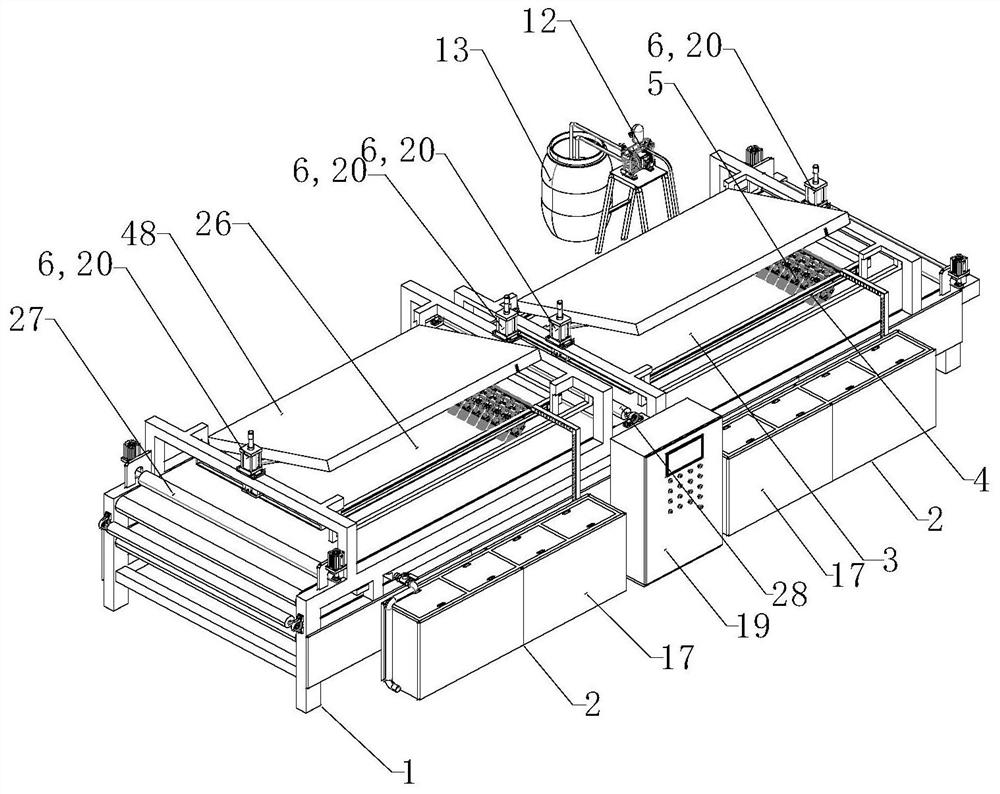
[0071] see Figure 1 to Figure 26 , the numerically controlled intelligent tie-dyeing machine of the present embodiment includes a frame 1, a dye bin assembly 2, a first conveyor belt 3 arranged on the frame, and a dyeing device above the first conveyor belt;

[0072] The dyeing device includes a mounting frame 4, a plurality of brushes 5 arranged on the mounting frame and a mounting frame lifting device 6 that drives the mounting frame to lift. There is a storage chamber 7 in the brush, and a connecting installation groove is provided on the inner wall of the storage chamber. With the discharge hole 8 of the storage cavity, the installation groove is used to install the bristles;

[0073] The dye bin assembly includes a plurality of dye bins 9, the dye bin is provided with a feeding tube 10, and the tube wall of the feeding tube is provided with a plurality of discharge holes 11, and the feeding tubes in each dye bin are transported through their respective The pump 12 commu...

Embodiment 2

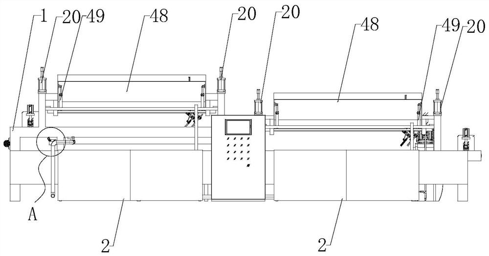
[0101] see Figure 27 , The CNC intelligent tie-dyeing machine of this embodiment adds the following technical content on the basis of the CNC intelligent tie-dyeing machine of Embodiment 1.

[0102] In the numerically controlled intelligent tie-dyeing machine of this embodiment, the installation frame is provided with an installation cross bar 52. In addition, an installation net 53 can also be provided. One end of the hair brush is arranged on the installation cross bar, and the other end of the hair brush can be arranged on the installation net. inside the mesh.

[0103] The arrangement of the installation cross bar and the installation net realizes the positioning and installation of the brush. The operator can arrange the brushes in the front and rear rows alternately through the installation net, so that the brushes in the front and rear adjacent rows will not affect each other, thereby increasing the installation density of the brushes.

[0104] In this embodiment, th...

Embodiment 3

[0106] see Figure 28 to Figure 32 , The CNC intelligent tie-dyeing machine of this embodiment adds the following technical content on the basis of the CNC intelligent tie-dyeing machine of Embodiment 1.

[0107] In the numerically controlled intelligent tie-dyeing machine of this embodiment, the installation frame is provided with an installation cross bar 52 and a guide longitudinal bar 54, and the installation cross bar is provided with a sliding seat 55 which slides and cooperates with the installation cross bar and the guide longitudinal bar respectively. on the sliding seat.

[0108] The brushes are respectively connected to the installation cross bar and the guide longitudinal bar through the sliding seat, so that the operator can adjust the position of the brush by moving the installation cross bar or the guide longitudinal bar. Wherein the sliding seat is used for connecting the guide longitudinal bar and installing the cross bar, and at the same time realizes the in...


PUM


Abstract

The invention relates to a numerical control intelligent tie-dyeing machine. The machine comprises a rack, a dye bin assembly, a first conveying belt arranged on the rack and a dyeing device located above the first conveying belt; the dyeing device comprises a mounting frame, and a plurality of brushes arranged on the mounting frame; the dye bin assembly comprises a plurality of dye bins; feeding pipes are arranged in the dye bins; the feeding pipes in the dye bins are communicated with corresponding dye barrels through respective conveying pumps; a plurality of dye output holes are formed in the bin walls of the dye bins; the dye output holes are connected with first electromagnetic valves through pipelines; and the dye output holes of the dye bins are communicated with corresponding dye output pipes after being output through the respective first electromagnetic valves. According to the numerical control intelligent tie-dyeing machine, through the arrangement of the dye bins and the first electromagnetic valves, output control over dyes of all colors is achieved, so that the dyes of specific colors can be output; and meanwhile, through the arrangement of the multiple brushes, cloth can be accurately dyed, and the dyeing effect is better.

Description

technical field [0001] The invention relates to a tie-dyeing machine, in particular to a numerically controlled intelligent tie-dyeing machine. Background technique [0002] Tie-dyeing is a dyeing method in which the fabric is tied up with thread and then printed and dyed. It is generally printed and dyed on the surface of the fabric by hand. This manual mode has high labor intensity and low printing and dyeing efficiency, and is not suitable for large-scale production. For this reason, some manufacturers have designed equipment capable of automatic tie-dyeing, such as the tie-dyeing equipment with the publication number "CN107805902A" and the name "a continuous tie-dyeing machine", which has a relatively simple structure and can only print and dye relatively simple patterns. It is impossible to carry out fixed-point and quantitative output of dyes to print and dye fabrics with different colors and patterns. Another tie-dyeing device, such as the Chinese patent with the pu...

Claims


Application Information

Patent Timeline
Patent Type & Authority Applications(China)
IPC IPC(8): D06B1/12D06B23/04D06B23/30D06B21/00D06B23/26B65H45/101
CPCD06B1/12D06B23/04D06B23/30D06B21/00D06B23/26B65H45/101
Inventor 解志杰解治田解志勇
Owner 常州智源万达软件有限公司
Why Eureka
Try Eureka