Jet flow force measuring method of netting cleaning disc
A technology for cleaning discs and nets, which is applied to the measurement of fluid pressure, testing of machine/structural components, and measuring devices, and can solve the problem of accurately measuring the impact force of circular cylindrical or cone-shaped cavitation jets on net cleaning discs and other issues to achieve high reliability, improve measurement accuracy, and improve reliability
- Summary
- Abstract
- Description
- Claims
- Application Information
AI Technical Summary
Problems solved by technology
Method used
Image
Examples
Embodiment 1
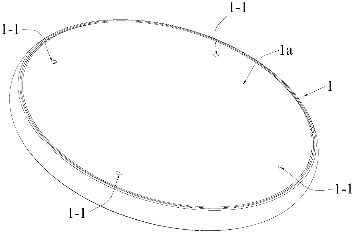
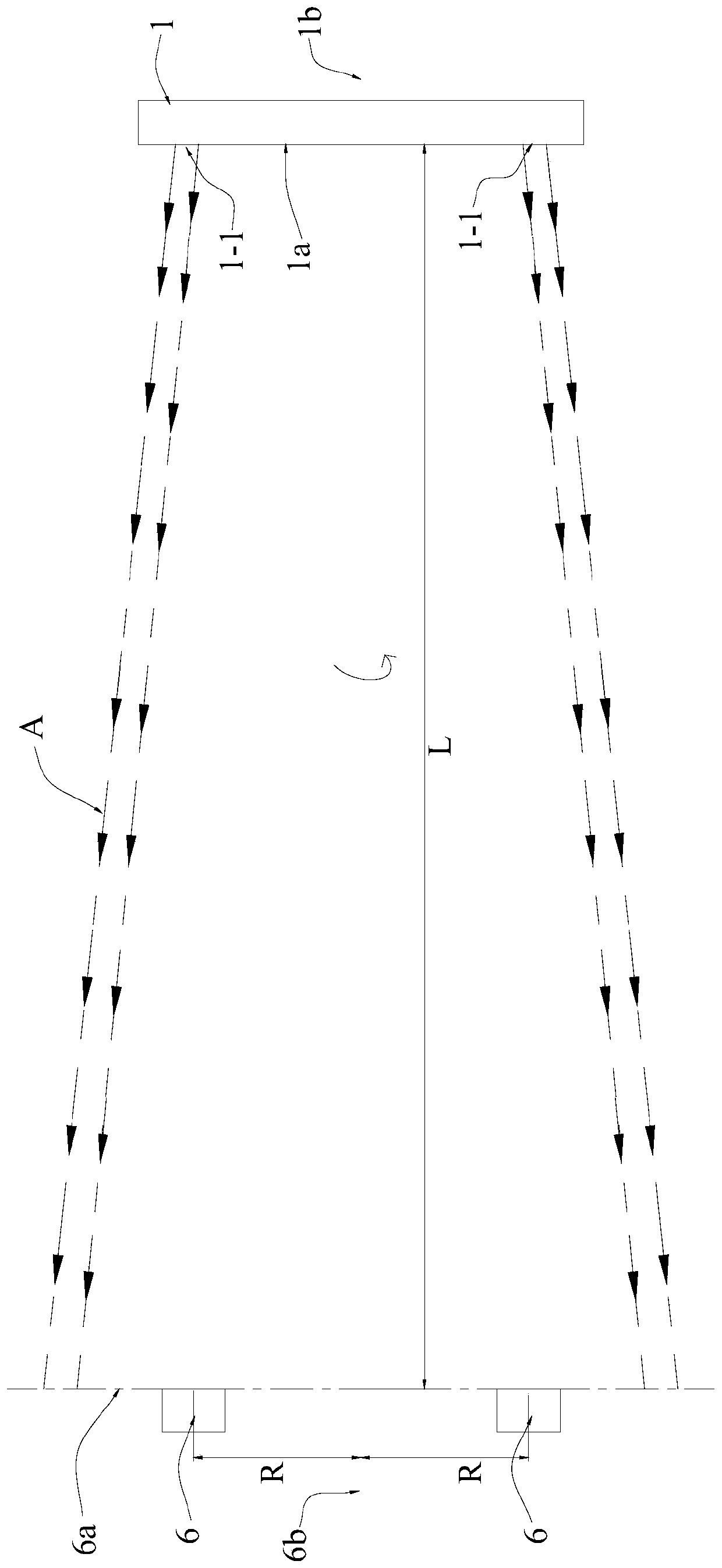
[0035] Such as Figure 1 to Figure 5 As shown, the present invention discloses a jet force measuring method for a net clothes cleaning tray, which is applicable to a net clothes washing tray 1 provided with a plurality of nozzles 1-1 on the end surface 1a, wherein each of the nozzles 1-1 is Arranged obliquely to the end face 1a of the net washing tray 1, and each of the nozzles 1-1 is arranged around the axis 1b of the net washing tray 1, so that: in the working state of the net washing tray 1, That is, when the net clothes cleaning fluid is sprayed from each of the nozzles 1-1, the net clothes cleaning disc 1 can rotate around its axis 1b under the rotation torque formed by spraying the net clothes cleaning fluid, so that all the nozzles 1 -1 The sprayed net clothing cleaning fluid forms a circular cylindrical or conical cavitation jet A;
[0036] The jet force measuring method includes:
[0037] Step 1. Install the tested net clothes cleaning tray 1 on the cleaning tray supp...
Embodiment approach
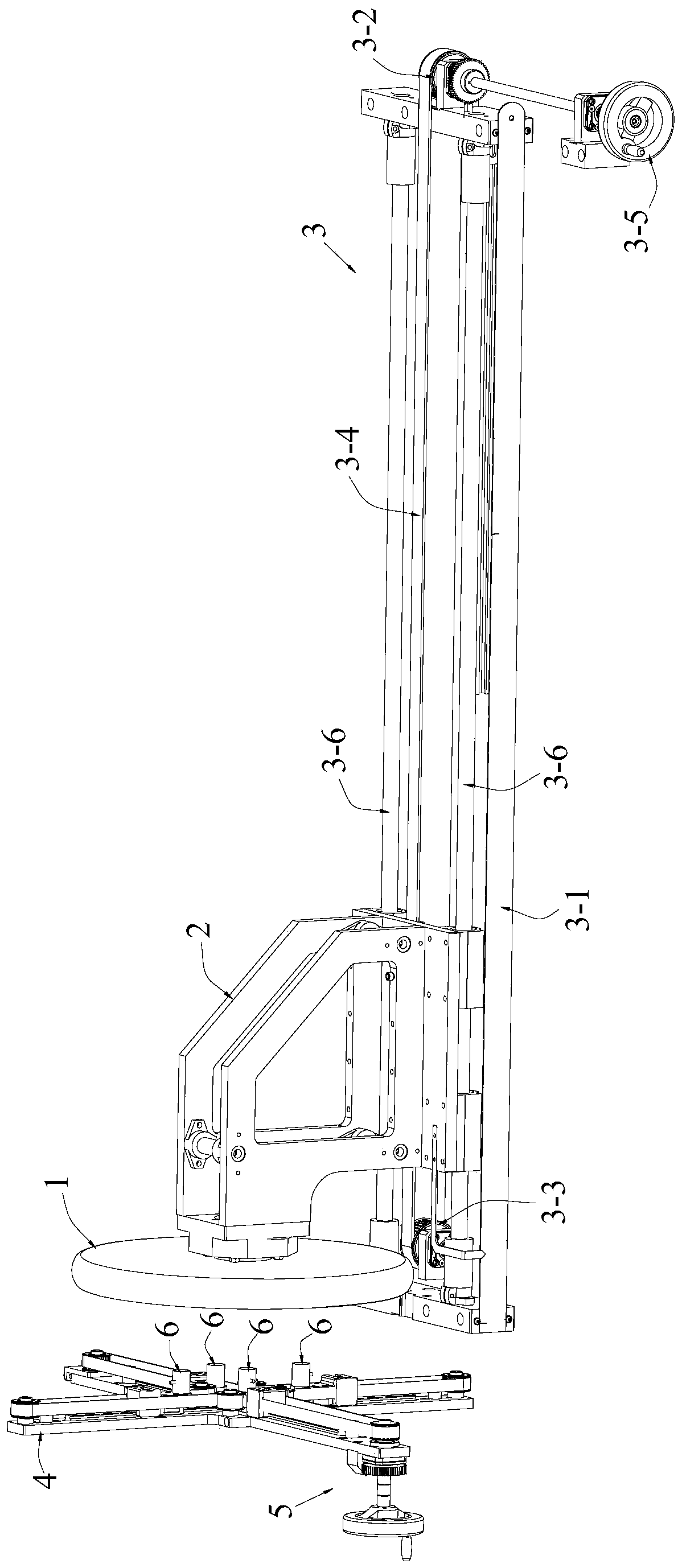
[0047] The jet force measuring device is provided with four pressure sensors 6; the front end of the sensor bracket 4 is provided with four linear tracks 4a arranged in a cross-shaped orientation, and the center positions of the four linear tracks 4a are located in the center On the axis 6b; the sensor moving mechanism 5 includes four sliders 5-1, four timing pulleys 5-2, four guide rollers 5-3 and a timing belt 5-4; the four sliders 5 -1 are respectively slidably installed on the four linear rails 4a, and the four pressure sensors 6 are respectively fixed on the four sliders 5-1; the four synchronous pulleys 5-2 and the four guide rollers 5-3 are respectively rotatably installed on the sensor bracket 4, and the four synchronous pulleys 5-2 are respectively located at the outer end positions of the four linear tracks 4a, and the clips between the adjacent two linear tracks 4a Only one guide roller 5-3 is arranged at the angular position, and each guide roller 5-3 is arranged c...
Embodiment 3
[0054] On the basis of the above-mentioned embodiment 1 or embodiment 2, this embodiment 3 also adopts the following preferred implementation modes:
[0055] The cleaning disc support moving mechanism 3 includes a base 3-1, a driving synchronous pulley 3-2, a driven synchronous belt pulley 3-3, a second synchronous belt 3-4, a cleaning disc driving handwheel 3-5 and guide rails 3-6; the driving synchronous pulley 3-2 and the driven synchronous pulley 3-3 are respectively rotatably installed on the base 3-1, and the second synchronous belt 3-4 is connected end to end and respectively connected with The driving synchronous pulley 3-2 is meshed with the driven synchronous pulley 3-3, the cleaning disk driving hand wheel 3-5 is coaxial and fixedly connected with the driving synchronous pulley 3-2, and the guide rail 3-6 is fixed on the base 3-1, and the guide rail 3-6 is parallel to the axis 1b of the net clothes washing tray 1; the washing tray support 2 is slidably connected to ...
PUM
 Abstract
Description
Claims
Application Information
 - R&D
- Intellectual Property
- Life Sciences
- Materials
- Tech Scout
- Unparalleled Data Quality
- Higher Quality Content
- 60% Fewer Hallucinations
Browse by: Latest US Patents, China's latest patents, Technical Efficacy Thesaurus, Application Domain, Technology Topic, Popular Technical Reports.
© 2025 PatSnap. All rights reserved.Legal|Privacy policy|Modern Slavery Act Transparency Statement|Sitemap|About US| Contact US: help@patsnap.com


