Polarity direct envelope inversion method based on seismic trace attribute analysis

A technology of attribute analysis and seismic trace, applied in the field of geophysical exploration, can solve problems such as lack of signal polarity information

Active Publication Date: 2020-06-05
XIAN UNIV OF TECH
View PDF6 Cites 2 Cited by
  • Summary
  • Abstract
  • Description
  • Claims
  • Application Information

AI Technical Summary

Problems solved by technology

However, the direct envelope inversion only depends on the instantaneous amplitude information of the seismic signal and lacks the polarity information of the signal. In order to further improve the inversion effect, it is necessary to use the direct envelope inversion method with polarity, and the accurate polarity information Acquisition is the key to the correct implementation of inversion

Method used


Image

  • Polarity direct envelope inversion method based on seismic trace attribute analysis
  • Polarity direct envelope inversion method based on seismic trace attribute analysis
  • Polarity direct envelope inversion method based on seismic trace attribute analysis

Examples


Embodiment Construction

[0060] The present invention will be described in detail below in conjunction with the accompanying drawings and specific embodiments.

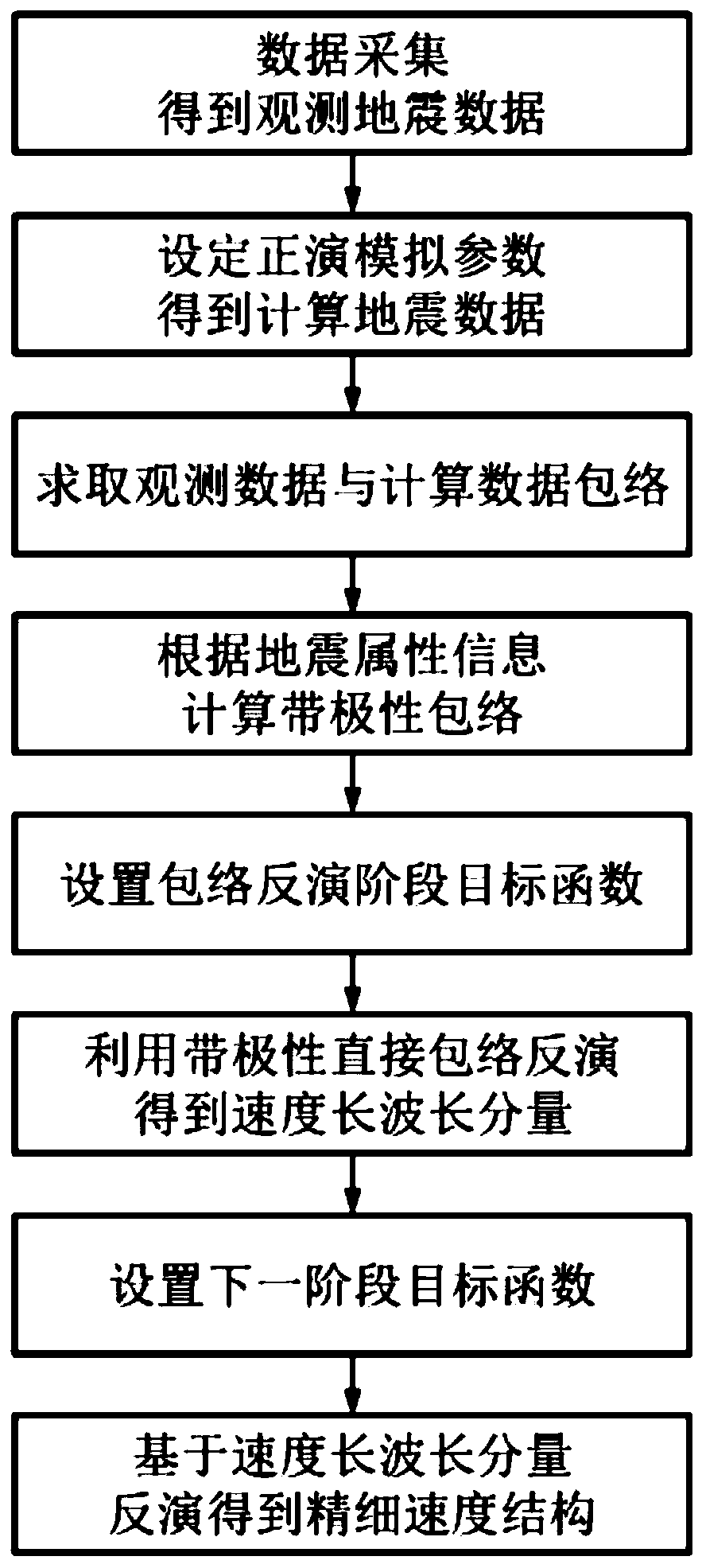
[0061] In the present invention, a polarized direct envelope inversion method based on seismic trace attribute analysis, such as figure 1 As shown, the specific steps are as follows:

[0062] Step 1. Set the shot point and receiver point, and collect the observation data u obs (t,x r ; x s ), where t represents the time variable; x r ,x s Respectively represent the location of the receiver point and the shot point;

[0063] Step 2. Construct a rectangular grid geological model, set the number of horizontal grid points Nx and the number of vertical grid points Nz of the model, and set the spatial sampling interval, time sampling interval dt, and maximum sampling time Nt of the forward modeling. Sampling interval includes horizontal sampling interval dx and vertical sampling interval dz;

[0064] Step 3. The initial velocity model v for ...


PUM


Abstract

The invention discloses a polarity direct envelope inversion method based on seismic trace attribute analysis, and the method specifically comprises the steps: 1, setting a shot point and a detectionpoint, and carrying out the collection to obtain observation data uobs(t, xr, xs); 2, constructing a rectangular grid geologic model; 3, giving the initial speed model v0(x) of the speed model v(x) toobtain calculation data ucal(t, xr, xs); 4, solving an envelope eobs(t, xr, xs) of the observation data and an envelope ecal(t, xr, xs) of the calculation data; 5, solving phases and instantaneous frequencies of the observation data and the calculation data; 6, solving the polar envelope of the observation data uobs(t, xr, xs) and a polar envelope given target function Je(v(x)) of the calculationdata ucal(t, xr, xs); 7, optimizing the target function Je(v(x)) through direct envelope inversion and iterative optimization algorithms to obtain a long-wavelength component vl(x) of the speed model; 8, giving a new to-be-optimized objective function J(v(x)) of the next stage; and 9, optimizing the target function J(v(x)) to obtain a fine speed structure vf (x). According to the method, a more accurate polar envelope can be obtained, and the method is used for inversion of a strong scattering speed model.

Description

technical field [0001] The invention belongs to the technical field of geophysical exploration, and in particular relates to a polarized direct envelope inversion method based on seismic trace attribute analysis. Background technique [0002] Oil and natural gas are important strategic resources related to national economic development and national security. With the development of the petroleum industry and the deepening of exploration and development, the exploration difficulty gradually increases from the stage of structural exploration to the stage of lithology exploration. In order to meet this requirement, full waveform inversion has developed rapidly and has become a research hotspot in the field of geophysics today. Full waveform inversion is an effective method to estimate formation parameters. It can not only provide high-resolution and high-precision velocity models for seismic imaging, but also has the ability to invert various parameters simultaneously. [0003...

Claims


Application Information

Patent Timeline
IPC IPC(8): G01V1/30G01V1/28
CPCG01V1/303G01V1/282
Inventor 罗静蕊王婕卢金波
Owner XIAN UNIV OF TECH
Why Eureka
Try Eureka