Light guide film, production method thereof and light guide device

A technology of light guide film and production process, which is applied in the direction of light guide, optics, optical components, etc., which can solve the problems of unfavorable long-term use and easy detachment, and achieve the effect of strong damage resistance, strong stretch resistance, and not easy to damage

Pending Publication Date: 2020-06-05
HANGZHOU XINENG NEW MATERIAL CO LTD
View PDF20 Cites 1 Cited by
  • Summary
  • Abstract
  • Description
  • Claims
  • Application Information

AI Technical Summary

Problems solved by technology

[0004] However, the above-mentioned scheme also has certain defects. Since the transparent film and the transparent substrate are separately arranged, the firmness of the bonding will be considered when the two are bonded together. The contact between the transparent substrate is not the bonding between the surface and the surface, but the bonding between the point and the surface. Although there are many light guide points, the transparent film and the transparent substrate are not the same material, and the bonding between the point and the surface is still It is easier to detach, which is not conducive to long-term use

Method used


Image

  • Light guide film, production method thereof and light guide device
  • Light guide film, production method thereof and light guide device
  • Light guide film, production method thereof and light guide device

Examples


Embodiment 1

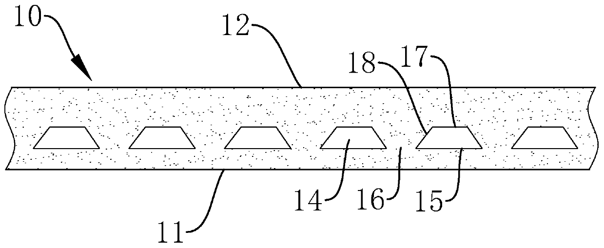
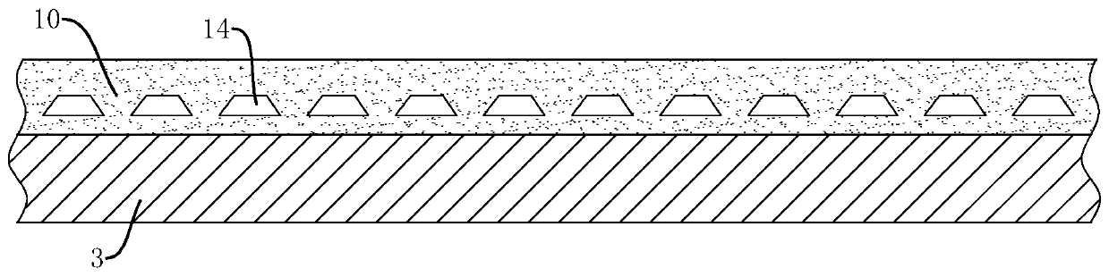
[0053] see figure 1 , a light guiding film 10, the upper surface of the light guiding film 10 is a light exit surface 12, and the lower surface is a light incident surface 11; the lower surface of the light guiding film 10 is smoothly arranged, and is used for fixed connection with the substrate 3 ( see figure 2 ); said light guiding film 10 is provided with several hollow ultramicrostructures 14, the side of said hollow ultramicrostructures 14 close to the lower surface of light guiding film 10 is a conducting and reflecting surface 15, every two adjacent ultramicrostructures The gaps between structures 14 are light exit gaps 16 .

[0054] In this embodiment, the lower surface of the light guide film 10 is set to be smooth, so that when it is fixed with the substrate 3, the entire surface can be bonded, the contact area can be maximized, and the fixing effect can be optimal, and the two are not easy to separate.

[0055] In this embodiment, the hollow ultramicrostructure 1...

Embodiment 2

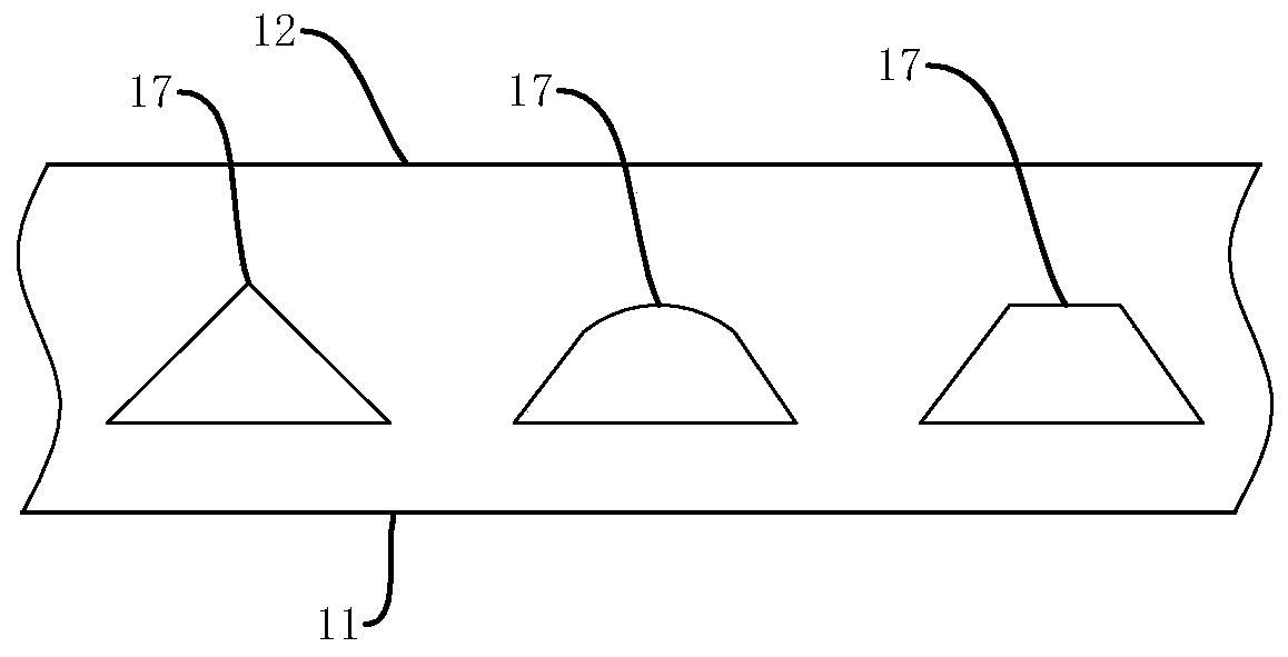
[0070] The difference between this embodiment and Embodiment 1 is that in this embodiment, the light-emitting reflection surface 18 is an arc-shaped surface.

[0071] Such as Figure 8 Shown is the light emitting line in Embodiment 1 when the light emitting reflective surface 18 is a slope. When the light hits the inclined surface, it is reflected and directed to the light emitting surface 12. Since the angles of the light directed to the inclined surface are different, the angles of the light emitted to the light emitting surface 12 after reflection are also different, and the intensity of the emitted light will be different.

[0072] In this example, if Figure 9 As shown, the light-emitting reflective surface 18 is set as an arc-shaped surface. When the light-emitting reflective surface is a curved surface, the angle between the tangent surface at any point on the curved surface and the light-incident surface is 45°-85°. By designing the angle of the arc surface, after th...

Embodiment 3

[0075] This embodiment provides a production process for a hollow ultra-microstructured light-guiding film, which is used to produce the light-guiding film of Example 1, and its production steps are as follows:

[0076] 1) Select the raw material, the raw material of the light guide film is optical grade transparent silica gel;

[0077] 2) Select a mold that is consistent with the shape of the light guide film (with an ultra-structure core mold);

[0078] 3) Inject the silicone raw material into the mold and shape it through the silicone molding process.

[0079] The integrally formed light guide film has a simpler process, and the hollow ultra-microstructure is set inside the light guide film. While guiding light, it is not easy to damage itself and has stronger tensile resistance.


PUM


Abstract

The invention relates to a light guide film, a production method thereof and a light guide device. The upper surface of the light guide film is a light emitting surface, and the lower surface is a light incident surface. The lower surface of the light guide film is smoothly arranged and is used for being connected with a substrate. A plurality of hollow ultramicro structures are arranged in the light guide film, the sides, close to the lower surface of the light guide film, of the hollow ultramicro structures are conduction reflection faces, and a gap between every two adjacent ultramicro structures is a light emitting gap. According to the invention, the lower surface of the light guide film is smooth, so that when the light guide film is fixed with the substrate, the whole surface fitting can be realized, the contact area is maximum, the fixing effect can be optimal, and the light guide film and the substrate are not easy to separate. Meanwhile, the ultrastructure is arranged in thelight guide film, so that light guide can be realized, the ultrastructure is not easy to damage, and the damage resistance is stronger.

Description

technical field [0001] The invention relates to the field of light-guiding materials, more specifically, it relates to a light-guiding film, a production method thereof, and a light-guiding device. Background technique [0002] Light guide structures are commonly found in light guide plates, which are high-tech products that convert linear light sources into surface light sources. Use optical-grade acrylic / PC boards, and print light guide points on the bottom surface of the boards with engraving printing technology. The optical-grade acrylic plate is used to absorb the light emitted from the light source, and the light is continuously reflected inside the plate. When the light hits each light guide point, the reflected light will spread to all angles, and then destroy the reflection condition and be emitted from the front of the light guide plate. . Through light guide points of various densities and sizes, the light guide plate can be made to emit light evenly. [0003] ...

Claims


Application Information

Patent Timeline
Patent Type & Authority Applications(China)
IPC IPC(8): G02B6/00
CPCG02B6/0015G02B6/0041G02B6/0065G02B6/0055G02B6/0061G02B6/0028G02B6/0053
Inventor 佘晓峰胡克勍
Owner HANGZHOU XINENG NEW MATERIAL CO LTD
Why Eureka
Try Eureka