Supercharge Your Innovation With Domain-Expert AI Agents!

Diffractive optical element, projection device and design method for projecting oblique lines

A technology of diffractive optical element and design method, applied in the field of optics, can solve the problems of poor visual effect of light field and poor visual effect of target image, and achieve the effect of improving aesthetics and neat and regular oblique lines.

Active Publication Date: 2020-12-29
JIAXING UPHOTON OPTOELECTRONICS TECH CO LTD
View PDF6 Cites 0 Cited by
  • Summary
  • Abstract
  • Description
  • Claims
  • Application Information

AI Technical Summary

Problems solved by technology

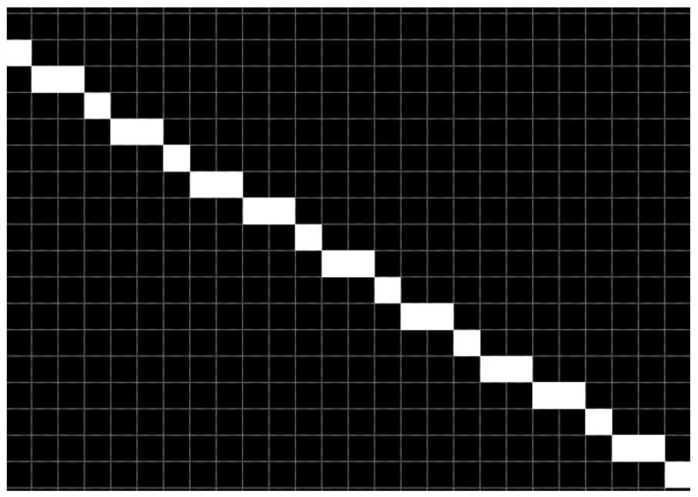
However, the inventors of the present application have found that when using the traditional method to design a diffractive optical element, if a diagonal line (except 45°) is drawn with a pixel width, the diagonal line will present an obvious jagged shape, such as figure 1 As shown in , the generated object map has poor visual effect, which leads to poor visual effect of the light field projected by the designed diffractive optical element

Method used

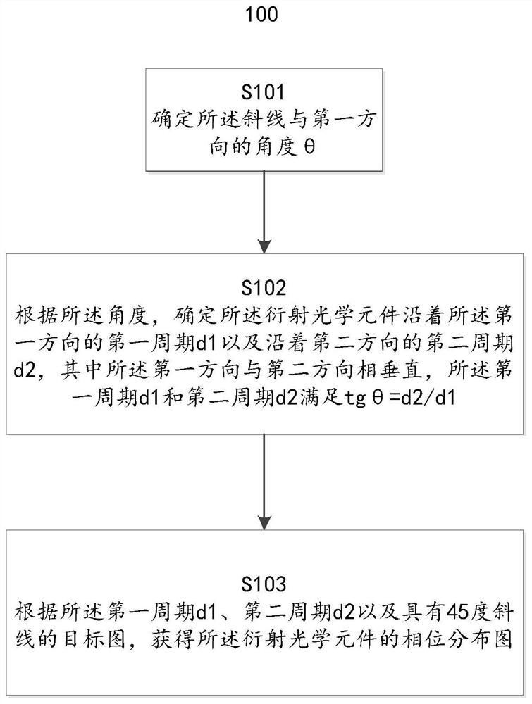
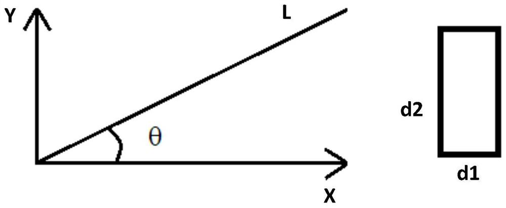

Image

  • Diffractive optical element, projection device and design method for projecting oblique lines
  • Diffractive optical element, projection device and design method for projecting oblique lines
  • Diffractive optical element, projection device and design method for projecting oblique lines

Examples


Embodiment Construction

[0032] In the following, only some exemplary embodiments are briefly described. As those skilled in the art would realize, the described embodiments may be modified in various different ways, all without departing from the spirit or scope of the present invention. Accordingly, the drawings and descriptions are to be regarded as illustrative in nature and not restrictive.

[0033] In describing the present invention, it is to be understood that the terms "center", "longitudinal", "transverse", "length", "width", "thickness", "upper", "lower", "front", " Back", "Left", "Right", "Straight", "Horizontal", "Top", "Bottom", "Inner", "Outer", "Clockwise", "Counterclockwise", etc. or The positional relationship is based on the orientation or positional relationship shown in the drawings, which is only for the convenience of describing the present invention and simplifying the description, rather than indicating or implying that the referred device or element must have a specific orie...


PUM


Abstract

The invention discloses a design method of a diffractive optical element that can be used to project an oblique line, including: determining the angle θ between the oblique line and a first direction; A first period d1 in a first direction and a second period d2 along a second direction, wherein the first direction is perpendicular to the second direction, the first period d1 and the second period d2 satisfy tgθ=d1 / d2; and According to the first period d1, the second period d2 and the target diagram with a 45-degree oblique line, the phase distribution diagram of the diffractive optical element is obtained. According to the embodiments of the present invention, the visual effect of the light field projected by the diffractive optical element can be improved.

Description

technical field [0001] The invention relates to the field of optical technology, in particular to a diffractive optical element capable of projecting oblique lines, a projecting device and a design method thereof. Background technique [0002] In the traditional design method, the diffractive optical element is designed to have multiple microstructure pattern units arranged in a two-dimensional array, each microstructure pattern unit has the same phase distribution pattern, and the Period is square. When designing a diffractive optical element that projects a diagonal pattern, in some application scenarios it is required that the line width of the projected pattern be as small as possible, such as for laser scanning guns (for special applications, the thinner the line, the better, not 45 degrees slash) indicates the situation of the pattern. Therefore, in the design process of the diffractive optical element, when making the target map, a diagonal line target map with only...

Claims


Application Information

Patent Timeline
Patent Type & Authority Patents(China)
IPC IPC(8): G02B27/00G02B27/42G06K7/10
CPCG02B27/0012G02B27/4205G06K7/10831G06K7/10881G02B5/1861G02B5/1847G06K7/10633G06K7/10683G02B27/4233
Inventor 王燚言田克汉
Owner JIAXING UPHOTON OPTOELECTRONICS TECH CO LTD
Features
  • R&D
  • Intellectual Property
  • Life Sciences
  • Materials
  • Tech Scout
  • Unparalleled Data Quality
  • Higher Quality Content
  • 60% Fewer Hallucinations
Learn More