
A planar microwave energy transmission window

A microwave energy transmission and planar technology, which is applied to the coupling device of the transit time type electron tube, etc., can solve the problems of unfavorable and impossible integration of high-frequency electric vacuum devices

Active Publication Date: 2021-07-13
UNIV OF ELECTRONICS SCI & TECH OF CHINA
View PDF21 Cites 0 Cited by
  • Summary
  • Abstract
  • Description
  • Claims
  • Application Information

AI Technical Summary

Problems solved by technology

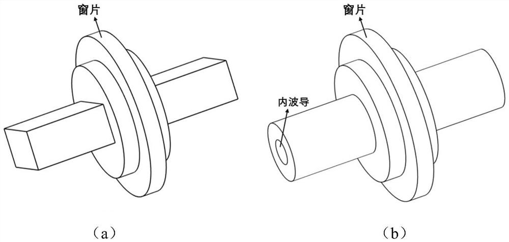
As an important part of microwave electric vacuum devices, traditional microwave energy transmission windows such as figure 1 The box window shown in (a) and the figure 1 The coaxial window etc. shown in (b), such as figure 1 As shown, they are all three-dimensional structures, using cylindrical windows, and their assembly method makes them impossible to integrate, which is unfavorable for the integration of high-frequency electric vacuum devices

Method used


Image

  • A planar microwave energy transmission window
  • A planar microwave energy transmission window
  • A planar microwave energy transmission window

Examples


Embodiment Construction

[0023] Specific embodiments of the present invention will be described below in conjunction with the accompanying drawings, so that those skilled in the art can better understand the present invention. It should be noted that in the following description, when detailed descriptions of known functions and designs may dilute the main content of the present invention, these descriptions will be omitted here.

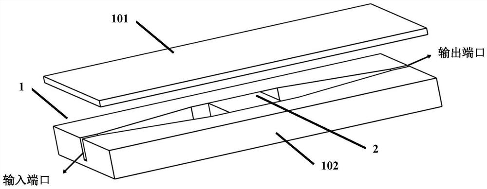
[0024] figure 2 It is a structural schematic diagram of a specific embodiment of the planar microwave energy transmission window of the present invention.

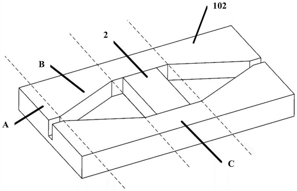
[0025] In this example, if figure 2 As shown, the planar microwave transmission window of the present invention includes a rectangular waveguide 1 and a window 2 . figure 2 It is also a simple assembly diagram of the planar microwave energy transmission window. actually figure 2 The upper cover plate 101 and the lower half part 102 are tightly welded. The input port and the output port are connected to the wave...


PUM


Abstract

The invention discloses a planar microwave energy transmission window. Different from the traditional cylindrical window, the window is designed to be flat, and its height (thickness) is consistent with the height of the broad side of the waveguide, and remains unchanged. The middle size of the narrow side of the waveguide is larger than the size of both ends, and the window is loaded in the middle of the narrow side of the waveguide, so that the height corresponding to the vacuum window and the wide side of the waveguide remains unchanged, and only changes in the direction of the narrow side, so that the microwave energy transmission The window is flat, that is, the 2-D structure with constant width side height greatly saves space and is more conducive to integrated applications. In addition, it avoids the cumbersome process in the assembly process of the traditional microwave energy transmission window and the slow-wave structure, and facilitates integration with the slow-wave structure; the loading space reserved for the flat window becomes larger, which is beneficial to the processing of the window in the extremely high frequency band.

Description

technical field [0001] The invention belongs to the field of microwave electric vacuum technology, and more specifically relates to an energy transmission structure of an electric vacuum device, that is, a planar microwave energy transmission window. Background technique [0002] In the microwave transmission systems of various microwave electron tubes, electron linear accelerators, electron-positron colliders, spallation neutron sources, plasma heating devices, etc., various microwave energy transmission windows are widely used, and their functions are mainly to separate The high vacuum environment and atmospheric environment inside and outside the tube play the role of isolation between the inside and outside, ensuring the internal vacuum environment, and at the same time transmitting microwave power with the lowest possible loss. The performance of the microwave energy transmission window structure directly affects the bandwidth, power, reliability and life of microwave e...

Claims


Application Information

Patent Timeline
Patent Type & Authority Patents(China)
IPC IPC(8): H01J23/42
CPCH01J23/42
Inventor 范五洋黄佳琪杨睿超徐进吴钢雄岳玲娜殷海荣赵国庆王文祥魏彦玉
Owner UNIV OF ELECTRONICS SCI & TECH OF CHINA
Learn More