
Auxiliary device for directional pickup microphone hanging and user identity confirmation and tracking method

An auxiliary device and user technology, applied in the direction of digital data authentication, sensors, electrical components, etc., can solve problems such as troublesome maintenance, large size, and inconsistent usage of internal equipment, and achieve the effect of convenient use efficiency and convenient later maintenance

Inactive Publication Date: 2020-06-05
江苏中协智能科技有限公司
View PDF9 Cites 0 Cited by
  • Summary
  • Abstract
  • Description
  • Claims
  • Application Information

AI Technical Summary

Problems solved by technology

However, this kind of equipment is generally large in size, and the utilization rate of its internal equipment is inconsistent, and maintenance is more troublesome.

Method used


Image

  • Auxiliary device for directional pickup microphone hanging and user identity confirmation and tracking method
  • Auxiliary device for directional pickup microphone hanging and user identity confirmation and tracking method

Examples


Embodiment 1

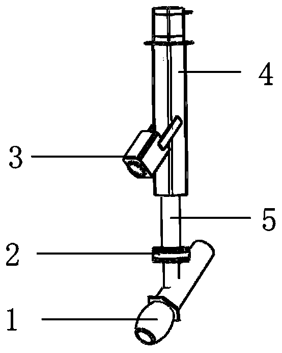
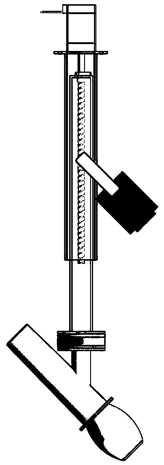
[0035] The auxiliary device for directional pickup and hanging of the microphone in this embodiment, such as figure 1 , 2 As shown, it includes a height adjustment mechanism, a driving mechanism, a transmission mechanism, and an identification mechanism.

[0036] Wherein, the height adjustment mechanism includes a fixed part and a movable part. The top of the fixing part is fixed to the roof and extends from the roof to the room. The movable part and the fixed part are kinematic pairs, and a cloud platform is installed at the bottom of the movable part. There is a hanging mic fixedly connected under the gimbal, and the gimbal is driven by the gimbal motor to drive the hanging mic to rotate. To meet the needs of realizing the tracking microphone function.

[0037] The driving mechanism drives the transmission mechanism to drive the height adjustment mechanism to realize the horizontal height change of the hanging wheat, and the transmission mechanism is used to drive the he...

Embodiment 2

[0047] The difference between this embodiment and Embodiment 1 is that the transmission mechanism in this embodiment adopts a pneumatic / hydraulic method, which has achieved the purpose of moving the movable part up and down. Specifically, the movable part performs ascending and descending operations by means of air pressure / hydraulic pressure. The corresponding driving mechanism is driven by a pneumatic unit if it is air pressure, and driven by a hydraulic motor if it is hydraulic. The rest of the settings can be properly adjusted according to Embodiment 1

Embodiment 3

[0049] The difference between this embodiment and the third embodiment is that the ball screw is replaced by a rack and pinion structure, and the others are basically the same or adaptively adjusted.


PUM


Abstract

The invention relates to an auxiliary device for directional pickup microphone hanging and a user identity confirmation and tracking method, and belongs to the technical field of directional pickup ofpickup microphones. The auxiliary device for directional pickup microphone hanging comprises a height adjusting mechanism, a driving mechanism, a transmission mechanism and an identity recognition mechanism. The height adjusting mechanism comprises a fixed part and a movable part; a holder is arranged at the bottom end of the movable part; a hanging microphone is fixedly connected with the holder. The lifting of the hanging microphone is realized through the driving mechanism. The identity recognition mechanism comprises an identity information acquisition device, an information comparison database, a recognition judgment module / device and an audio adjustment module / device; the identity information acquisition device is mounted on the outer side of the bottom of the fixed part. Accordingto the invention, equipment simplification is realized through omnibearing sensing and the holder, the use is convenient, the efficiency is improved, and the maintenance is convenient. And the intentional user is separated from the user, and the identity recognition is limited in a use state and a non-use state, so that the practical application of teaching sound amplification is facilitated.

Description

technical field [0001] The invention relates to an automatic lifting microphone and a corresponding identification and judgment method, belonging to the technical field of sound pickup microphones. Background technique [0002] The hanging mic is generally installed at a fixed position on the ceiling. Except for special circumstances (such as in 201822144814.9 "A Teaching Recording and Broadcasting System", the hanging mic can move on the slide rail in a certain way), and the position of the hanging mic generally does not change. [0003] The original intention of applying hanging microphones to teaching sound reinforcement is to free hands for teachers to teach easily and for the sake of teachers' health. [0004] With the application of hanging microphones in teaching sound reinforcement, teachers are more free in the teaching process, but hanging microphones added to the teaching sound reinforcement system for the purpose of freeing hands have become obstacles that limit ...

Claims


Application Information

Patent Timeline
IPC IPC(8): H04R1/08G06F21/32
CPCG06F21/32H04R1/083
Inventor 陆伟家原晓孟樊辉罗志强
Owner 江苏中协智能科技有限公司
Features
  • Generate Ideas
  • Intellectual Property
  • Life Sciences
  • Materials
  • Tech Scout
  • Unparalleled Data Quality
  • Higher Quality Content
  • 60% Fewer Hallucinations
Learn More