Separating system of a flue-gas desulfurization system of a ship

A separation system and exhaust gas desulfurization technology, applied in the field of separation systems, can solve the problems of plates no longer functioning correctly, pollution, etc., and achieve the effects of reducing oil, shortening the structure height, reducing oil and pollution

Inactive Publication Date: 2020-06-05
德特勒夫韦伯
View PDF0 Cites 0 Cited by
  • Summary
  • Abstract
  • Description
  • Claims
  • Application Information

AI Technical Summary

Problems solved by technology

[0022] Oily contamination thus causes the corre

Method used


Image

  • Separating system of a flue-gas desulfurization system of a ship
  • Separating system of a flue-gas desulfurization system of a ship
  • Separating system of a flue-gas desulfurization system of a ship

Examples


Embodiment Construction

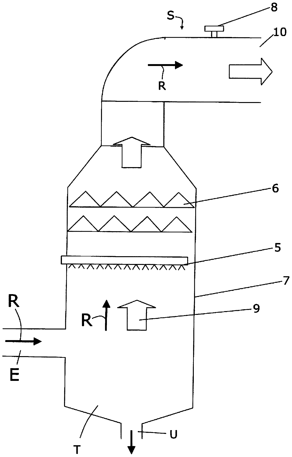
[0062] The prior art separation system shown in FIG. 1 comprises a container 7 through which an exhaust gas flow 9 is guided in flow direction R, that is to say from bottom to top. To this end, the container 7 has a lateral inlet E. Below the lateral inlet E, the container 7 comprises a tank T for collecting liquid. At the deepest point of the tank T there is provided an outlet U through which the collected liquid can be drained off and possibly fed to a further use device or a cleaning device. In the container 7, the exhaust gas flows through the spraying device 5, with which the liquid is delivered in the form of a spray in the exhaust gas for the reaction with SO 2 or SO 3 Combine and wash out the solid. Formed already absorbed SO 2 or SO 3 and droplets of solid components. They are washed out by means of a droplet separator arranged downstream of the spraying device in the flow direction of the exhaust gas. Most of them fall down in the container 7 due to gravity an...


PUM


Abstract

The invention relates to a separating system of a flue-gas desulfurization system of a ship for separating drops (11) from a flue gas, which flows in a flow direction (R), preferably with a flow component directed vertically upward, and which exits through the outlet opening of a smokestack, said separating system comprising at least one plate (1), which is elongate in a longitudinal direction (L)and the longitudinal direction (L) of which is oriented perpendicularly or obliquely to the flow direction (R), the plate (1) comprises at least one chamber (2) having an opening (2a) extending in the longitudinal direction (L), the opening (2a) being arranged on a side of the plate (1) facing the flow direction (R).

Description

technical field [0001] The invention relates to a separation system of exhaust gas desulfurization equipment of a ship. On the one hand, the separation system should ensure that a ship equipped with the separation system complies with the requirements of new discharge regulations at sea. On the other hand, the separation system should overcome the known problems of chimney rain (intensive discharge of liquid droplets from wet chimneys). Furthermore, the separation system should minimize contamination of the components following the droplet separator (in the direction of the exhaust gas flow) taking into account the operating experience of the past few decades. [0002] Exhaust gases from diesel-ignited marine engines are mainly desulphurized in order to be discharged from the stack according to wet scrubbing methods. For this purpose, the sulfur-containing exhaust gas is guided through a container which is located in front of the chimney in the direction of flow of the exhau...

Claims


Application Information

Patent Timeline
IPC IPC(8): B01D45/08
CPCB01D45/08B63H21/32
Inventor 德特勒夫·韦伯
Owner 德特勒夫韦伯
Why Eureka
Try Eureka