Auxiliary exercise device for recovery of orthopaedic patient

An exercise device and patient technology, applied in sports accessories, muscle training equipment, gymnastics equipment, etc., can solve the problems of bone dislocation of patients, limit and fixation of patients' legs and feet, and achieve improved comfort and good protection , easy to switch effects

Active Publication Date: 2020-06-09
QINGDAO MUNICIPAL HOSPITAL
View PDF9 Cites 6 Cited by
  • Summary
  • Abstract
  • Description
  • Claims
  • Application Information

AI Technical Summary

Problems solved by technology

However, this device cannot limit and fix the patient's legs and feet. When the patient is exercising, the legs or feet will be misaligned due to force, which will lead to more serious bone misalignment in the patient.

Method used


Image

  • Auxiliary exercise device for recovery of orthopaedic patient
  • Auxiliary exercise device for recovery of orthopaedic patient
  • Auxiliary exercise device for recovery of orthopaedic patient

Examples


specific Embodiment approach 1

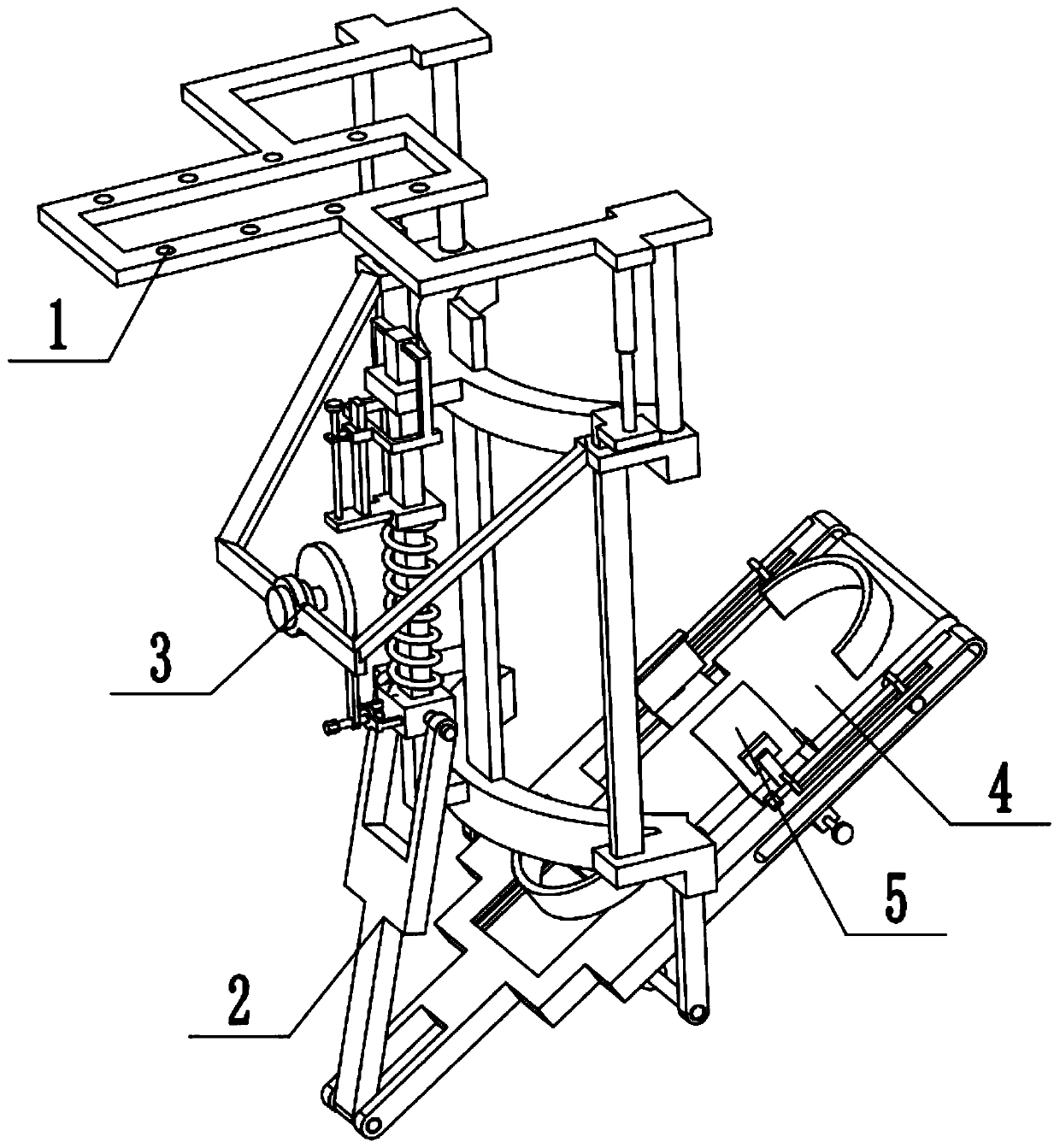
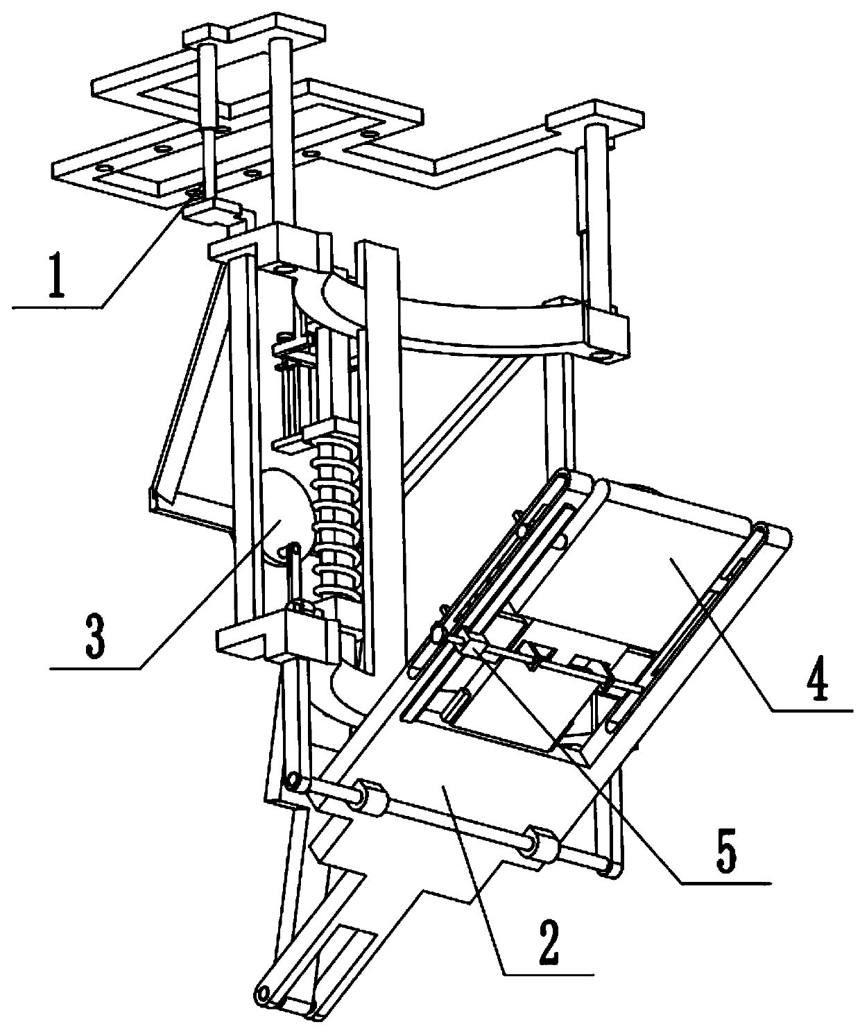
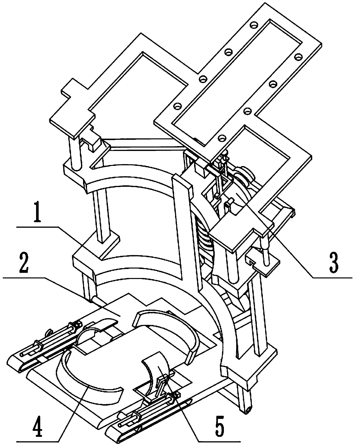
[0031] Combine below Figure 1-10 Describe this embodiment, a recovery auxiliary exercise device for orthopedic patients, including a leg support frame 1, a foot rehabilitation mechanism 2, an automatic drive mechanism 3, a foot telescopic adjustment member 4 and a foot fixing mechanism 5, the foot The foot rehabilitation mechanism 2 is connected with the leg support frame 1, and the foot is stepped on. The foot rehabilitation mechanism 2 actively exercises the ankle joint, and the automatic driving mechanism 3 is arranged on the leg support frame 1. The health mechanism 2 is matched and connected, and the automatic driving mechanism 3 drives the foot rehabilitation mechanism 2 to automatically drive the foot to swing. The adjustable position on the mechanism 2 is suitable for soles of different sizes, and the foot fixing mechanism 5 is connected with the foot telescopic adjustment member 4 in cooperation. When in use, when the automatic driving mechanism 3 is separated from ...

specific Embodiment approach 2

[0033] Combine below Figure 1-10 To illustrate this embodiment, the leg support frame 1 includes a top frame plate 1-1, a connecting rod 1-2, an upper arc frame 1-3, a lower arc frame 1-4, a slide bar 1-5, an electric Telescopic rod 1-6, baffle plate 1-7, rotating shaft frame 1-8, rotating shaft 1-9 and sliding sleeve 1-10; Top frame plate 1-1 is provided with a plurality of screw jacks, and upper arc frame 1- 3. The two connecting rods 1-2 are fixedly connected to the top frame plate 1-1, and the lower arc frame 1-4 is fixedly connected to two sliding rods 1-5, and the two sliding rods 1-5 are respectively slidably connected to the At the two ends of the upper arc frame 1-3, two electric telescopic rods 1-6 are located at the two ends of the top frame plate 1-1 respectively, and the telescopic ends of the two electric telescopic rods 1-6 are connected with the two slide rods 1 respectively. -5 is fixedly connected, and the lower arc frame 1-4 is fixedly connected to the baf...

specific Embodiment approach 3

[0035] Combine below Figure 1-10 To illustrate this embodiment, the foot rehabilitation mechanism 2 includes a fork-shaped bottom plate 2-1, a side chute 2-2, an upper chute 2-3, a cross-shaped chute 2-4, and a heel top seat 2- 5. Articulating arm 2-6, slider 2-7, vertical bar 2-8, spring seat 2-9, insert plate 2-10, fixed frame 2-11, screw rod 2-12, compression spring 2-13, screw The insert 2-14 and the trapezoidal slide rail 2-16; the lower end of the fork base plate 2-1 is rotatably connected on the rotating shaft 1-9, and the right end of the fork base plate 2-1 is symmetrically provided with two side slide grooves 2-2, There are two upper chute 2-3 on the right end top surface of the fork base plate 2-1; the side chute 2-2 communicates with the upper chute 2-3; the middle part of the fork base plate 2-1 is provided with a cross-shaped The chute 2-4, the heel top seat 2-5 are fixedly connected to the middle part of the fork base plate 2-1, the left end of the fork base p...


PUM


Abstract

The invention discloses an auxiliary exercise device for recovery of an orthopaedic patient, and relates to the technical field of medical auxiliary instruments. The auxiliary exercise device comprises a leg supporting frame, a foot rehabilitation mechanism, an automatic driving mechanism, a foot telescopic adjusting piece and a foot fixing mechanism. and the device has the following advantages: the leg and foot of a patient can be limited and fixed, and the foot and leg are well protected. The foot rehabilitation mechanism is connected to the leg supporting frame in a matched mode, the foot treads the foot rehabilitation mechanism and actively exercises the ankle joint, the automatic driving mechanism is arranged on the leg supporting frame, the automatic driving mechanism is connected with the foot rehabilitation mechanism in a matched mode, the automatic driving mechanism drives the foot rehabilitation mechanism to automatically drive the foot to swing, the foot telescopic adjustingpiece is arranged on the foot rehabilitation mechanism, the position of the foot telescopic adjusting piece on the foot rehabilitation mechanism can be adjusted to be suitable for soles of differentsizes, and the foot fixing mechanism is connected with the foot telescopic adjusting piece in a matched mode.

Description

technical field [0001] The invention relates to the technical field of medical auxiliary equipment, in particular to a recovery auxiliary exercise device for orthopedic patients. Background technique [0002] Patent No. CN201720404432.8 is a pedal-type ankle joint exerciser for lower limbs. This utility model discloses a pedal-type ankle joint exerciser for lower limbs, which includes a base, a baffle, a pedal, two pillars, a drive shaft, and a power device. , a transmission device, two resistance devices, a baffle plate is set at one end of the base, and two pillars are arranged side by side in the middle of the base, the two pillars are symmetrical about the central axis of the exerciser, and a drive shaft is set on the two pillars, and the drive shaft The two ends of the two pillars are rotatably connected to the two pillars, the pedals are set on the two pillars through the drive shaft, the drive shaft passes through the pedals in the horizontal direction, the power devi...

Claims


Application Information

Patent Timeline
Patent Type & Authority Applications(China)
IPC IPC(8): A63B23/08A63B23/10A63B21/05A63B21/00A63B71/00
CPCA63B21/00178A63B21/05A63B23/08A63B23/10A63B71/0054
Inventor 易子钧
Owner QINGDAO MUNICIPAL HOSPITAL
Why Eureka
Try Eureka